
Magnetic Fuses
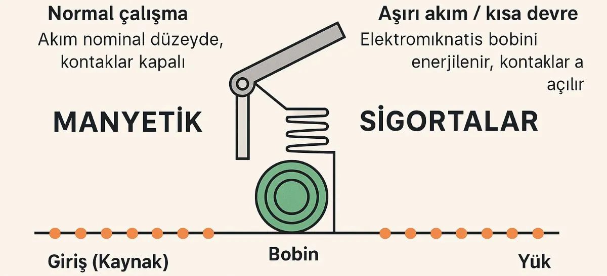
How high fault current releases the trip mechanism
The phrase magnetic fuse is sometimes used loosely for a circuit breaker with an electromagnetic trip mechanism. High fault current strengthens the coil’s magnetic effect, releases the mechanism and separates the contacts. The device does not prevent a short circuit; it interrupts the fault current to help limit damage.
Editor’s note: a conventional fusible-element fuse must be replaced after operation. A circuit breaker can be reset after the fault has been cleared and its suitability for continued service checked. An instantaneous magnetic-only trip does not provide sustained overload protection. Understanding these differences between protective devices prevents selection errors.
The coil, operating mechanism and arc chamber
Load current passes through a series coil. At sufficiently high current, magnetic force moves a core or armature, releasing the latch; stored spring energy rapidly separates the contacts. Opening contacts produce an arc. In low-voltage air circuit breakers, an arc chute splits and cools it to help interrupt the current. The correct term is arc chute or arc chamber, rather than an arc furnace.
Magnetic and thermal protection have different roles
Magnetic tripping responds rapidly to high fault currents. Thermal tripping responds to the heating caused by sustained overload; higher overload currents generally produce shorter trip times. Thermal-magnetic circuit breakers combine both functions. A motor circuit using instantaneous magnetic-only protection also needs an appropriate overload relay or equivalent overload protection.
Hydraulic-magnetic circuit breakers are a separate design. A core moving through fluid provides a delay, allowing these devices to protect against overloads as well as short circuits. Establish the actual protective functions from the manufacturer’s trip curve and product data, rather than the name alone.
Opening the contacts breaks the current path
This shows a simplified section of a phase conductor, rather than a wiring design or a real-time measurement. Start shows the closed contacts and moving current trace. Show magnetic trip opens the contacts and removes that trace. Stop only stops the moving trace. The blue dashes do not represent AC electrons travelling continuously in one direction.
What B, C and D trip curves mean
For common AC miniature circuit breakers covered by IEC 60898-1, the instantaneous magnetic trip bands are 3–5 × In for B, 5–10 × In for C and 10–20 × In for D. In is the rated current. These letters distinguish the magnetic threshold band; a C or D marking does not mean that thermal protection is absent.
C16 example: the rated current is 16 A and the instantaneous magnetic band is 80–160 A. This does not mean the breaker can carry 80 A continuously or must trip at exactly 80 A. At lower overcurrents, its thermal element may operate. Assess the behaviour using current duration and the manufacturer’s tolerance band.
Selection requires more than an ampere rating
Select the rated current against both the load and the conductor’s permissible current, allowing for installation method, ambient temperature and grouping. When selecting protection, check breaking capacity separately: a 16 A current rating and a 6 kA short-circuit rating describe different capabilities. At the applicable voltage, the breaking capacity must cover the prospective short-circuit current at the installation point; verified backup-protection arrangements require separate assessment.
Check operating voltage, AC/DC suitability, pole configuration and trip curve together. For DC circuits, follow the manufacturer’s voltage, pole-connection and any polarity requirements. On devices covered by IEC 60947-2, Icu is the ultimate and Ics the service short-circuit breaking capacity. Their test conditions must not be confused with Icn under IEC 60898-1. Apply the relevant protection standards according to the device’s actual markings.
Motor circuits and residual-current protection
If starting current causes unwanted trips, simply increasing the ampere rating or choosing a D curve is insufficient. Conductor protection, starting duration and disconnection at the minimum fault current must be assessed together. Match the contactor, overload relay and short-circuit protective device using the manufacturer’s coordination tables.
Magnetic tripping does not replace a residual-current protective device intended for protection against electric shock. Protective earthing, overcurrent protection and residual-current protection perform different roles. Combined protection is available only where the device is specifically designed and marked for those functions.
Can a tripped breaker be reset?
Yes, provided the cause of operation has been identified and corrected. Isolate the supply safely, verify the absence of voltage and assess the connections and device against the manufacturer’s maintenance requirements. Burning, melting, mechanical damage or repeated tripping calls for investigation, rather than forcing the handle or repeatedly reclosing. The need for replacement also depends on fault severity and the manufacturer’s instructions. Work must follow appropriate electrical safety precautions.
Related pages: Types of protective devices / Fuses and protection products
Sources
ABB: thermal and magnetic tripping
ABB: SMISSLINE TP trip characteristics, pp. 2/17–2/18
Eaton: circuit breaker parts and comparison with fuses
Eaton: hydraulic-magnetic protection
Schneider Electric: thermal-magnetic versus magnetic-only protection
Schneider Electric Electrical Installation Guide: ratings and breaking capacity