
Liquid Filled Fuses
Understanding what the liquid actually does
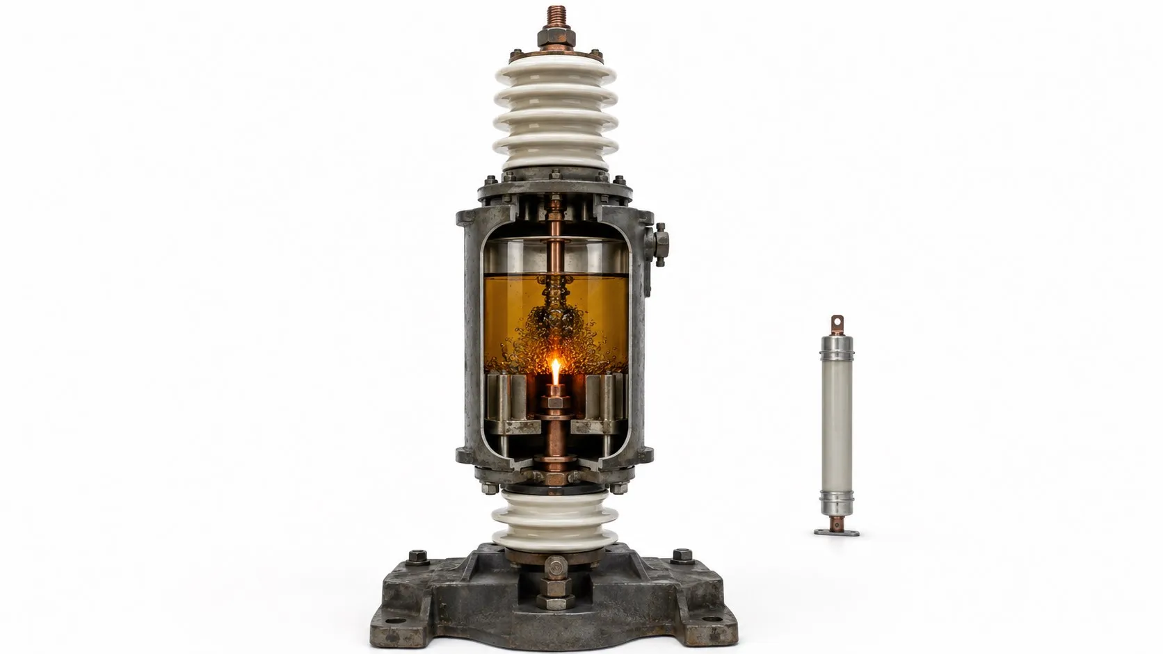
Hello everyone. A liquid-filled fuse is a particular fuse design that uses a liquid medium as part of its arc-interruption system. The term does not place every fuse used in an oil-filled transformer in the same category. To identify the right device, distinguish its internal construction, operating environment and interruption method. The basic fuse operating principle remains the same: an overcurrent of sufficient magnitude and duration melts an element, and the resulting arc must then be extinguished safely.
Editor's note: Operating under oil does not mean being filled with oil. For example, a sealed current-limiting fuse intended for oil immersion may contain sand internally. The word “liquid” therefore does not establish a high interrupting rating, fast operation or overload protection. These properties must be checked in the product documentation.
Liquid-filled designs and oil-immersed fuses
Historical liquid-filled designs: The original S&C Liquid Power Fuse used a spring mechanism inside a glass tube containing carbon tetrachloride. Melting of the element released the spring, which lengthened the arc while the liquid helped extinguish it. This example shows why every liquid-filled fuse cannot be described as an “oil-filled ceramic cartridge.” The historical liquid named here is not a recommendation for refilling equipment today.
Oil-immersed transformer fuses: Fuse arrangements such as Bay-O-Net, used in certain distribution transformers, are designed to operate in transformer fluid. In an appropriate protection scheme, this fuse can work in series with a current-limiting fuse. Immersion in the same liquid does not give the two devices the same interruption method or protection range. Understanding differences between fuse types directly affects product selection.
How the element melts and the arc is interrupted
The primary function of an electrical fuse is to limit the danger from overcurrent by interrupting the circuit. Heating of the element depends on current magnitude, duration, element geometry and heat transfer to its surroundings. The metal or alloy varies with the design. Silver and copper should not be described generally as “low-melting-point metals”; fuse behaviour cannot be explained by melting temperature alone.
After the element melts, current can continue briefly through an electric arc. Consequently, melting time and total clearing time are different quantities. A historical liquid-filled design may use a spring and liquid together, while a sand-filled current-limiting fuse uses a different arc-quenching arrangement. Liquid vaporisation is not a universal explanation of how every device in these groups operates.
Interrupting capability and protection coordination
The current rating concerns normal service conditions; the interrupting rating concerns the fault current the fuse can safely interrupt under specified conditions. They are not interchangeable. The prospective fault current established by a short-circuit study must remain within the fuse's interrupting capability at the applicable voltage. Some back-up current-limiting fuses also have a minimum interrupting current; another protective device is needed for lower overcurrents.
In a coordinated two-fuse transformer scheme, the Bay-O-Net can clear overloads and specified secondary faults, while the current-limiting fuse clears high fault currents. This describes a manufacturer's coordinated arrangement, not permission to connect any two fuses in series. Time-current curves, the transformer damage curve and other protective devices must be considered together. The factors involved in selecting a fuse extend beyond its amperage and dimensions.
What information is needed for selection?
Voltage and supply type: Check the operating voltage, frequency and the manufacturer's permitted voltage range. In particular, a medium-voltage current-limiting fuse with a higher voltage rating is not automatically suitable at every lower voltage. An AC-rated device must not be assumed suitable as a DC fuse; interruption on a DC circuit requires a separate assessment.
Load and thermal conditions: When determining the fuse current rating, consider transformer power, primary voltage, loading, energisation inrush and temperature. Fluid type and temperature, mounting orientation, holder compatibility and the manufacturer's derating requirements also matter. The same ampere rating does not mean the same protective behaviour.
Practical example: A three-phase transformer rated 1000 kVA with a 10 kV primary has a rated primary current of approximately 57.7 A: 1000 / (1.732 x 10). This does not automatically call for a 63 A fuse. Selection must allow normal magnetising inrush while clearing faults before the transformer's withstand limits are exceeded. If opening recurs, investigate why the fuse has blown; increasing its amperage is not an acceptable diagnosis.
Applications, advantages and limitations
The main application discussed here is transformer and distribution-system protection using suitable equipment designs. Compatibility with fluid immersion, compact installation or coordination with another fuse can be advantages of particular products. However, fluid compatibility, sealing integrity, replacement availability and the selection of equivalents for older equipment require attention. The presence of liquid does not, by itself, make protection faster, stronger or less demanding to maintain.
A machine having a high-power motor is not sufficient reason to specify a liquid-filled fuse. Motor overload, phase-loss and short-circuit protection must be selected for that motor's operating conditions. Likewise, a transformer fuse should not be regarded as a device guaranteed to detect every internal fault at its earliest stage.
Inspection, replacement and safe maintenance
When assessing whether a fuse needs replacement, inspect not only whether its element has opened but also the housing, leakage, connections and holder condition. An operated fuse does not identify the original fault on its own. Qualified personnel must follow the safety precautions for fuse replacement and the equipment instructions, including isolation of energy sources and verification that the equipment is de-energised. The specific load-switching capability of one assembly must not be assumed for every fuse.
Do not add an arbitrary liquid, repair the element with wire or bypass the protection. Verify the replacement's type code, characteristic, voltage range, interruption limits and mechanical compatibility together. Leaked or unidentified fluid must be assessed using the equipment documentation and the relevant safety data sheet.
Read standards according to the interruption method
Among the IEC standards for fuses, IEC 60282-1 covers high-voltage current-limiting fuses, while IEC 60282-2 covers high-voltage expulsion fuses. The latter term describes particular interruption arrangements that use gas flow produced during arcing. These scopes concern AC applications above 1000 V at 50/60 Hz. The description “liquid-filled” alone does not establish compliance with either standard or prove product certification.
Related fuse topics
Explore high-voltage fuses for voltage-class requirements, industrial fuses for plant applications, current fuses for overcurrent response, special-purpose fuses for application-specific designs and fast and slow-blow fuses for operating characteristics.
Transformers, measurement and complementary protection
The transformer operating principle and power transformers provide useful background, while current transformers explain how measurements are supplied to protection systems. Grounding affects fault-current paths and touch voltages. For motors on the low-voltage side, phase-protection relays can monitor loss of a phase and perform a different, complementary function.
Continue through the fuse guide
Use which type of fuse to choose, fuse standards and the main fuse product category to explore the related guidance and product range.
Sources
S&C: construction of the historical Liquid Power Fuse
Eaton: Bay-O-Net and two-fuse transformer protection
Mersen: high-voltage fuses, interruption ranges and selection principles
Mersen: medium-voltage transformer protection application information