
How is Ethernet/IP configured?
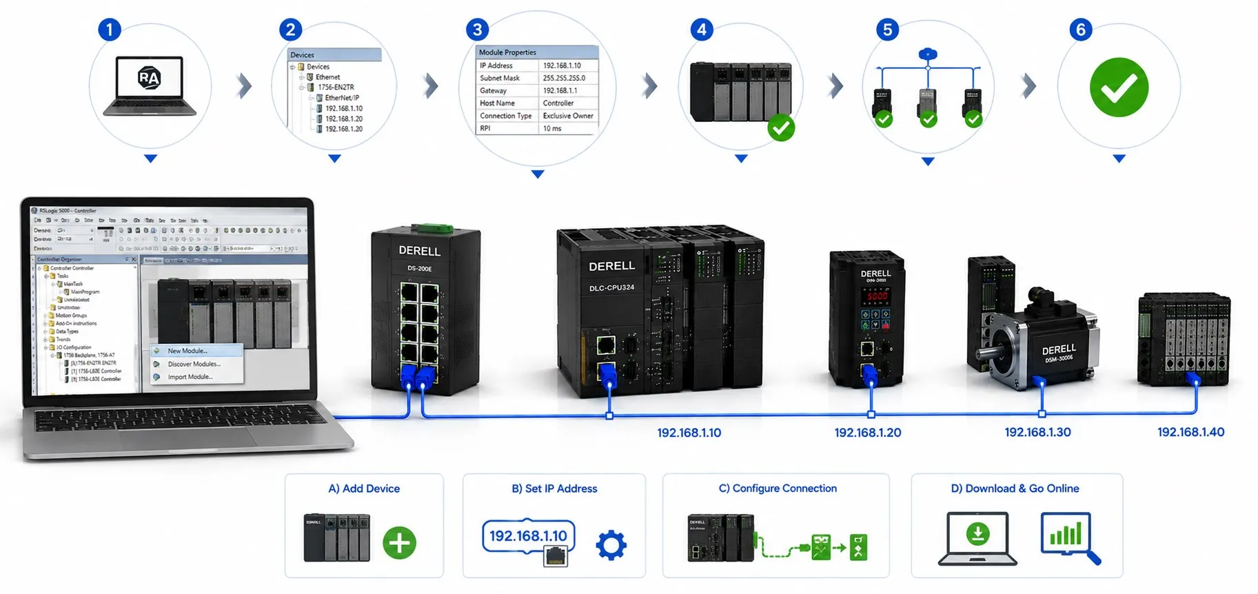
From an address plan to validated I/O communication
EtherNet/IP configuration brings together the physical network, IP addressing, device roles, I/O connections and application data. Discovering a device on the network does not establish that it exchanges the correct data with a PLC. A sound configuration defines what each device sends, how often data is updated and what happens when communication is lost.
Editor's note: A ping reply does not prove that an EtherNet/IP I/O connection is established or that commands are interpreted correctly. Check IP reachability, CIP connections and application data separately. A subnet mask is also not a firewall; access rules between networks require their own design.
Define the roles and required data
For cyclic I/O, a scanner/originator establishes a connection with a suitable adapter/target. Verify the roles supported by each device against its product code and communication option. Two devices offering only adapter functionality cannot establish a scanner connection using those functions alone. An HMI's ability to read PLC tags does not make it an I/O scanner.
Identify each device's commands, status, references, measurements and diagnostic data. Record the response requirements, connection count and control ownership for the industrial application. If several controllers use one device, check support for connection types such as exclusive owner, input-only or listen-only. Do not assume that multiple output owners are permitted.
Implicit I/O can carry cyclic commands and status, while explicit messaging can access supported parameter or diagnostic services. Assess settings and device support for these paths separately. An infrequently read parameter may not need a continuously transmitted I/O area; individual parameter queries also do not establish that fast I/O requirements have been met.
Prepare the physical network and topology
Select cables and connectors for the environment, movement, electromagnetic conditions and device ports. Check link length limits, shielding, grounding arrangements and switch power supplies. Base copper or fiber selection and star or line topology on the equipment's supported capabilities.
Two Ethernet ports do not establish support for every ring topology. A DLR network needs suitable devices and a ring supervisor function. Arbitrarily connecting the ends of an ordinary line can create a network loop. Monitor port speed, duplex status and error counters. Check device documentation for requirements concerning autonegotiation or fixed port settings.
Configure IP addresses, subnet masks and address assignment
Record the IP address, subnet mask, MAC address and device name together. For example, a simple cell within one VLAN could use 192.168.10.10 for the PLC, 192.168.10.20 for the adapter and 192.168.10.100 for the engineering computer, all with mask 255.255.255.0. Verify that these example addresses do not conflict with the site's existing plan. In this /24 network, .0 is the network address and .255 is the broadcast address; neither is assigned to a device.
Direct communication within the same subnet does not require a router. Access to other networks requires an appropriate default gateway and routing rules. Choose a supported method such as static configuration, DHCP, BOOTP or hardware address switches. With DHCP, use a reservation or suitable address management to preserve the address expected by the controller project.
Assigning an address through a commissioning tool alone does not guarantee that it will persist after a power cycle. Depending on the product, disable dynamic addressing, save settings to nonvolatile memory or maintain the server reservation. Verify addressing during a controlled restart test. Also check that the computer uses the correct Ethernet interface and that another device is not using the same IP address.
Use the correct EDS or device profile revision
Install the manufacturer's EDS file, device profile or supported Add-On Profile package in the relevant engineering environment. The method depends on the PLC platform. Check software and tool versions against the product catalog number and firmware. An EDS describes device characteristics and connection options; it does not automatically create the PLC application program.
When a supported generic device method is used, enter connection details from the device manual. On platforms with electronic keying, consider manufacturer, product code and revision checks. Resolve a mismatch through the correct device and profile pairing instead of casually disabling the check. Installing a profile and establishing the product's conformance and certification scope are separate matters.
Match assembly instances, data direction and sizes
Obtain the input assembly, output assembly and, where needed, configuration assembly instances from the product documentation for cyclic data exchange. From the PLC scanner's perspective, T→O is input data received from the adapter; O→T is output data sent from the PLC to the adapter. Distinguish the device's local input/output names from the PLC's network perspective.
Check the unit used for data size. For example, 32 bytes of user data correspond to 16 elements when using 16-bit elements, or 8 elements when using 32-bit elements. This calculation applies when the configuration field counts elements of that type. Check whether the software automatically adds protocol fields such as Run/Idle before manually adding them to a configured size.
Map PLC variables to the correct bit positions, integer signedness, REAL representation, byte order and scaling. Establishing a connection does not correct a misinterpreted speed or temperature value. Custom software must preserve the same data contract and provide the data consistency required by the application when handling results with multiple fields.
Select RPI and connection timeouts for the application
RPI, Requested Packet Interval, is the requested interval for cyclic packet transmission. It is different from the PLC program scan time and the overall sensor-to-actuator response time. Assess the device's supported range, controller capacity and latency requirements together. Some connections allow separate intervals for each direction.
For a single fixed-size cyclic stream, 20 ms means approximately 50 packets per second, while 5 ms means 200 packets per second. Packet frequency increases fourfold for the same data size. This calculation does not represent total Ethernet traffic or the response time of the complete system. The smallest RPI is not the best setting for every application. Configure connection timeouts and any timeout multiplier according to the manufacturer's rules.
Configure unicast, multicast and access rules
Select unicast or multicast according to device and connection support. Where multicast is used, assess IGMP snooping together with the IGMP querier arrangement in the relevant VLAN. Enabling snooping alone is insufficient network design. Apply product-specific requirements separately, such as the unicast selection in the relevant Universal Robots setup guide.
Include the EtherNet/IP ports and traffic types needed by the selected functions in firewall rules. Assess VLANs, user permissions and management access alongside supported security capabilities. Design network segmentation and access controls to allow required communication between authorized systems. VLAN membership alone does not provide user authentication or encryption.
Complete the device's application settings
A variable frequency drive needs more than a working network connection. Configure the command source, speed reference source, control word, status word and reference scaling for the selected communication profile. A drive in local control mode may not accept the expected command even when PLC data is correct. Acceleration, deceleration and enable conditions must also match the application design.
For remote I/O, check channel types and module order; for robots, check data areas and command handshakes. Define and test the behavior of outputs or the drive when communication is lost. A stop command through ordinary I/O does not automatically implement a safety function. Required machine safety functions need their own architecture and validation.
Commission the system at the data level
Check physical connectivity and IP reachability first, followed by device identity, I/O connection status and data validity. During diagnostics, distinguish incorrect assemblies, size mismatches, revision mismatches, connection ownership and timeouts. In a controlled test, observe a known input change in the PLC and compare an authorized output command with the actual device response.
Test scenarios such as cable disconnection, device restart, the PLC entering program mode and recovery to normal operation under planned conditions. A value remaining on the screen does not establish that new data is arriving. The application must use data quality and connection status. If SCADA or another supervisory system is involved, verify its communication-loss and recovery behavior too.
Complete integration, backups and change records
Connecting to another protocol such as Modbus TCP requires an appropriate gateway or middleware. Configure endpoint roles, data mapping and update intervals on both sides. A router alone does not translate application protocols. On a packaging line, for example, PLC connections to drives and remote I/O can have different requirements from the connection carrying production data to a supervisory system.
Back up the PLC project, device parameters, IP/MAC list, EDS/profile revisions and switch settings. If DHCP reservations are used, account for the new MAC address when replacing a device. A restore test matters alongside having a backup. Before firmware or software changes, establish compatibility and a rollback plan. Record the accepted configuration with its date and revision.
Related topics
Ethernet and EtherNet/IP differences
Ethernet fundamentals
Ethernet questions
PLC and HMI main page
Sources
ODVA: EtherNet/IP infrastructure and addressing
ODVA: Device Level Ring planning and supervisor functions
Rockwell Automation: IP assignment, BOOTP/DHCP and persistence
Rockwell Automation: electronic keying and device matching
Schneider Electric: assemblies, data directions, sizes and RPI settings
Universal Robots: scanner connection, RPI and unicast setup
ABB: FENA-01 control/status words and drive communication profiles
Cisco: industrial network design, multicast and IGMP
NIST SP 800-82 Rev. 3: OT network segmentation and access control