
Regenerative braking integration in servo drives
Regenerative Braking and Energy Recovery in Servo Drives
Hello colleagues,
Regenerative braking converts mechanical energy from a moving load into electrical energy that returns to the drive’s DC bus. The servo motor operates as a generator while the servo drive controls motor current and braking torque. Energy returning to the drive does not necessarily return to the AC supply.
Where does the braking energy go?
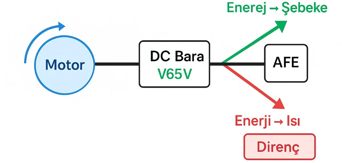
Motor → drive → DC bus is the common starting path. What happens next depends on the hardware: heat dissipation in a braking resistor, reuse by another axis on a shared DC bus, or return to the supply through a regenerative unit. These routes provide different functions and different energy savings.
Three routes for braking energy
Resistor braking: returned energy is dissipated as heat.
This illustration shows energy flow; it does not simulate hardware or bus voltage.
1. Why does a motor generate power while braking?
When motor torque opposes motion and the load continues moving, mechanical power can flow back into the electrical system. Speed and torque control manages this behavior. Load inertia, initial speed and deceleration time determine the returned energy and instantaneous power. Improving dynamic performance therefore also requires adequate braking capacity.
A descending load can return potential energy as well. Continuous regeneration and an occasional short stop impose different sizing requirements.
2. Does a braking resistor recover energy?
A braking chopper transfers energy to a suitable braking resistor when the DC bus reaches its configured operating threshold. The resistor converts this energy into heat, limiting the bus voltage rise. Resistor braking does not recover electrical energy for reuse.
Select resistance, peak power, average power and duty cycle together. Do not go below the drive’s permitted minimum resistance. Installation, ventilation and hot surfaces require appropriate thermal management. Not every servo drive includes a chopper or supports an external resistor.
3. How does an AFE return energy to the supply?
An active front end (AFE) or compatible regenerative supply module can transfer DC bus energy back to the AC supply under controlled conditions. A conventional diode rectifier cannot do this on its own. Returning motor energy to the DC bus and returning that energy to the supply are separate functions.
During motor and drive selection, check the supply topology, regenerative power rating, required reactors or filters and the manufacturer’s connection requirements. Power factor and harmonic performance depend on the design and operating point. Evaluate actual savings against the machine’s operating cycle when assessing energy efficiency.
4. What does a shared DC bus achieve?
In compatible servo systems, energy from a braking axis can feed another axis that is accelerating at the same time. Multi-axis coordination can help align these energy-producing and energy-consuming movements. A shared DC bus enables this exchange; it does not, by itself, feed energy back to the AC supply.
If all axes brake together, there may be no consuming axis. The remaining energy then needs a suitable resistor, regenerative unit or another supported management path. Follow the manufacturer’s requirements for voltage class, precharge, fuses and protection, wiring and combined current limits. Do not connect unrelated drives’ DC terminals arbitrarily.
5. Are bus capacitors an energy storage system?
DC bus capacitors temporarily hold a limited amount of energy. Their available energy window is approximately E = ½ × C × (V₂² − V₁²), within the permitted voltage range. Their presence does not mean a drive can store all braking energy or operate as an uninterruptible power supply.
Specialized supercapacitor or battery solutions require a compatible power converter, voltage management and storage control. These are not standard features of every servo drive. The appropriate solution depends on motor and system sizing.
6. How is braking energy calculated?
For a simplified rotating load, use E = ½ × J × (ω₁² − ω₂²). Here, J is equivalent inertia and ω is angular speed in rad/s; do not substitute rpm directly. The gearbox and transmission ratios affect the shaft to which the calculation refers. Include the relevant mechanical energy of linear or vertical loads as well.
Example: If a stop releases 6,000 J over 2 seconds, the average mechanical braking power during that stop is 3,000 W. If the stop repeats every 10 seconds, its cycle-average contribution is 600 W. Peak power, stopping-period average power and cycle-average power are different quantities. Account separately for losses and the manufacturer’s pulse-load limits.
7. How do the drive and controller manage braking?
Check deceleration ramps, current and torque limits, bus protection and any supported resistor parameters during servo drive configuration. The PLC can manage the operating cycle and fault responses. An EtherCAT servo system may expose bus voltage, torque and alarm information for monitoring; available data depends on the drive.
An encoder or resolver provides speed and position feedback for compatible motor control. Auto-tuning can help tune motion control loops; it cannot compensate for an undersized resistor or missing regenerative hardware. Validate repeated stops with the real load and monitor thermal behavior.
8. Final integration checks
Verify motor and load data, stopping frequency, the energy transfer path, bus voltage and thermal capacity as one system. Acceptance requires more than the motor stopping: the system must remain stable over repeated cycles and demonstrate its defined stopping behavior. Add wiring, connection and cooling checks to the servo maintenance plan.