
IEC 60947-7-3
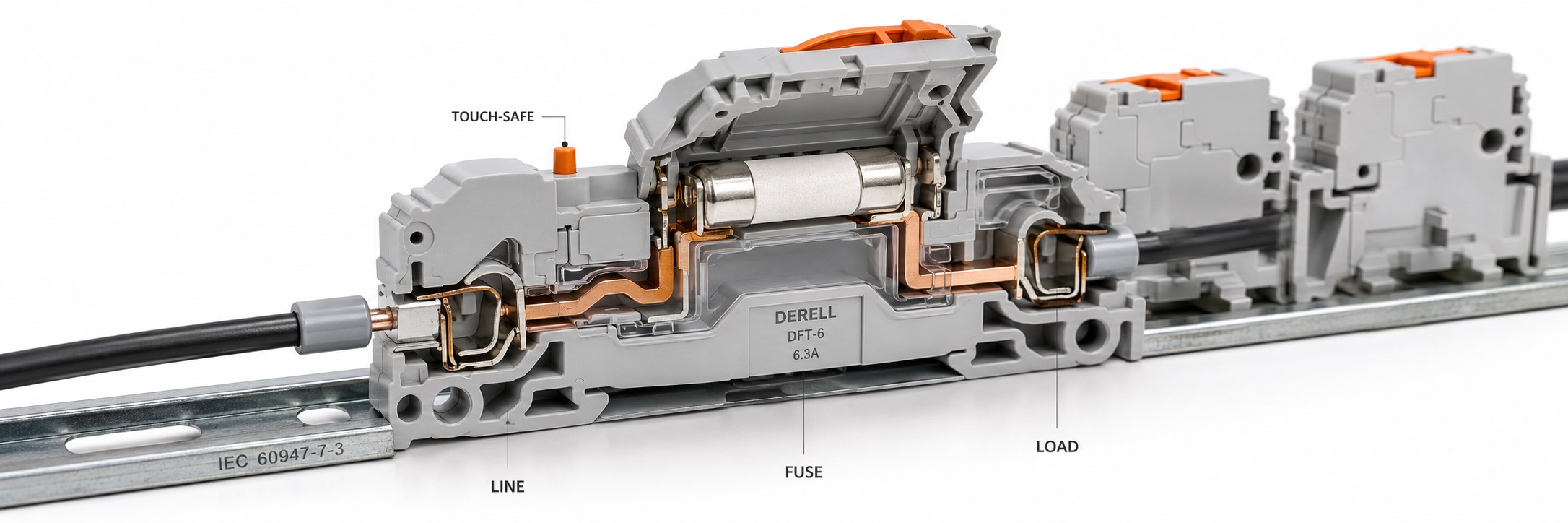
Assessing the fuse and its connection together
IEC 60947-7-3 addresses safety requirements for fuse terminal blocks. It covers screw and screwless connections for copper conductors and their mechanical, electrical and thermal compatibility with cartridge fuse-links covered by IEC 60127-2. The terminal block provides the connection and fuse holder; the appropriate fuse interrupts the overcurrent.
The scope extends to 1,000 V AC at up to 1,000 Hz or 1,500 V DC, with a maximum short-circuit breaking capacity of 1,500 A. These are scope limits, not universal product ratings. The usable voltage and current depend on the documented terminal block, fuse and indicator combination.
Editor's note: IEC 60947-7-1 concerns general terminal blocks, 7-2 protective conductor terminal blocks, 7-3 fuse terminal blocks, and 7-4 PCB terminal blocks. Classifying PCB connections under 7-2 leads to comparisons between the wrong products and documents.
Current rating is only part of the selection
The fuse current rating, terminal block current limit and holder's thermal limits must be assessed together. Two fuses with the same dimensions and current rating may have different power losses or operating characteristics. Select the fuse type and fast-acting or time-delay characteristic to suit the load's inrush current and the circuit being protected.
Permissible fuse power dissipation is easy to overlook. If a manufacturer permits a fuse loss of 1 W under specified conditions, a 2 W fuse cannot be selected simply because its size and current rating match. These figures are illustrative. Actual limits depend on ambient temperature, adjacent loaded terminals and the manufacturer's derating data. Weidmüller's data sheet gives different conditions for individual and grouped arrangements, illustrating why the installation matters.
For DC applications, check the fuse's breaking capacity at the relevant DC voltage and its compatibility with the terminal block. Operating voltage, impulse withstand voltage and breaking capacity describe different properties. A 6 kV impulse rating, for example, does not permit continuous operation at 6 kV. Electrical fuse selection also includes the prospective short-circuit current and coordination with upstream protection.
Indicators, conductors and installation details
On models with an LED or neon indicator, read the indicator operating voltage separately. The insulation rating, voltage between adjacent terminals and indicator supply range are different specifications. Some indicator circuits pass a small current, so compatibility with sensitive inputs needs attention. An unlit indicator does not prove that the circuit is de-energized.
After determining the conductor cross-section and current-carrying capacity, compare the product's permitted ranges for solid, stranded and ferruled conductors. Ferrules or bridging accessories can change the accepted cross-section. Screw and spring connections have different preparation requirements. Take the stripping length, tightening torque and accessory compatibility from the documentation for the exact part number; one model's torque is not a rule for every terminal block.
Distinguishing a fuse carrier from a load-switching device
An opening fuse carrier does not automatically provide load-breaking capability or a safe isolation function. Where that function is required, assess the manufacturer's explicit declaration, utilization category and the relevant IEC 60947-3 switching and isolating devices. Replace fuses in accordance with the installation's procedure for disconnecting the supply and verifying the absence of voltage.
IEC 60269 power fuses and IEC 60127-2 miniature cartridge fuses cannot be assumed to suit the same holder. Check the fuse family, voltage, breaking capacity and thermal compatibility as well as dimensions. A standard number on the terminal block also does not, by itself, establish conformity of the complete machine or assembly.
Reading documentation and edition references
IECEE's 60947-7-3C test report form dated 2023 applies to IEC 60947-7-3:2009 together with IEC 60947-1:2007. The report form's date is not a new edition of the standard. Trace the product code, standard edition, tested fuse arrangement and application restrictions through the relevant documents. Manufacturer examples illustrate the selection process; their ratings do not apply to every model.
Related subjects within the standard family
IEC 60947-1 general rules help explain ratings and common test concepts. Check the particular edition referenced by the project.
IEC 60947-2 circuit-breakers are relevant when assessing upstream protection and protective coordination for a fused outgoing circuit.
The IEC 60947-7 ancillary equipment family provides a starting point for matching a connection device's function to the appropriate part.
IEC 60947-7-1 terminal blocks for copper conductors address general connection requirements; the specific assessment of a fuse terminal block involves part 7-3.
IEC 60947-7-2 protective conductor terminal blocks cover PE and PEN connections. A protective conductor connection and a fused supply branch serve different functions.
Considering other components in the panel
For power supplies, output current limiting and short-circuit behaviour can affect fuse operating time. Assess the supply and branch protection together.
Separate branch protection for PLC supplies and I/O groups can help identify a faulty circuit. Select the fuse according to the module's permitted protection arrangement.
In contactor coil circuits, consider pickup current and coil voltage. A fuse terminal block in the control circuit does not replace motor power-circuit protection.
For photoelectric sensor supplies, check indicator leakage current and supply range to avoid misleading fault diagnosis.
On inductive sensor circuits, assess the common supply, individually fused branches and conductor sizes together. Sensor load current and circuit fault current are different quantities.
Explore related product groups through fuses and control devices.
Sources: IEC and IECEE scope information and manufacturer documentation from Phoenix Contact, Weidmüller and Klemsan. Sources checked: 17 October 2026.
IEC 60947-7-3:2009 official scope; IECEE 60947-7-3C:2023 test report form; IEC 60947-7-2 protective conductor terminal blocks; IEC 60947-7-4 PCB terminal blocks.
Phoenix Contact TB 4-HESI technical data; Weidmüller KDKS 1PE/LLC data sheet; Klemsan ASK 3 MLD 48 VDC technical data.