
AS/NZS 4509.1
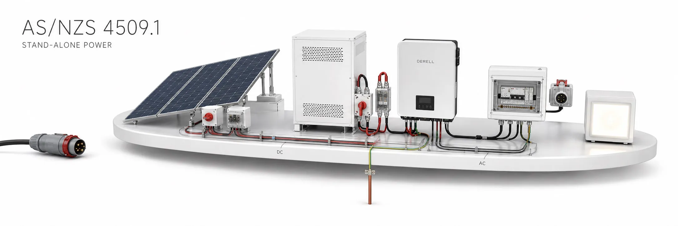
Building a safe independent power supply
Hello everyone. AS/NZS 4509.1 is a joint Australian and New Zealand standard addressing safety and installation requirements for stand-alone power systems. Its scope can include systems supplying a water pump, one building or a group of buildings. It is not limited to solar panels: arrangements incorporating batteries, inverters, wind or hydro generation and generating sets are assessed according to the system concerned.
Editor's note: AS/NZS 4509.1 concerns safety and installation, while AS/NZS 4509.2 concerns system design. Presenting panel sizing and storage-capacity calculations as the main subject of Part 1 is incorrect. A system can produce enough energy while still having inadequate electrical protection.
Understanding scope and edition information
The standard covers extra-low-voltage (ELV) and low-voltage (LV) supplies. It addresses equipment up to the system output and direct connections from that output to loads or electrical installations. Its published scope specifically includes supply-conductor ratings, overcurrent protection and earthing arrangements. The scope of design Part 4509.2 centres on domestic systems with energy storage at ELV; applying its principles elsewhere does not make its scope unlimited.
Catalogue check on 15 October 2026: AS/NZS 4509.1:2009 and the design part, AS/NZS 4509.2:2010, are listed as current. The Australian 2017 reconfirmation record does not mean that a new 2017 edition was published. The applicable edition and amendments must also be checked against the regulatory references governing the project's location.
Energy capacity and electrical power are different
A 3 kW load operating for two hours requires an ideal 3 × 2 = 6 kWh of energy. The difference between kW and kWh matters when selecting an inverter and battery. The inverter must support continuous power and starting demands, while the battery must meet usable-energy and current requirements.
Battery-capacity calculations consider conversion losses, permitted depth of discharge, temperature and ageing allowances. A demand of 6 kWh therefore does not directly justify selecting a battery labelled 6 kWh. Calculating runtime from an ampere-hour rating also requires voltage and operating conditions. These are design assessments; installation safety and protection must be assessed separately.
Low battery voltage does not mean low current
Consider an inverter delivering 5 kW of AC power from a 48 V battery, assuming 90% efficiency. Approximate DC input current is 5,000 / (48 × 0.90) = 116 A. At 24 V, the same assumptions give approximately 231 A. Actual current varies with battery voltage and efficiency. This illustrates the importance of cables and connections; it is not a direct method for selecting a fuse rating.
Selecting a DC fuse or circuit breaker involves more than its ampere rating. DC voltage rating, interrupt capacity and operating characteristic must also be suitable. A battery's prospective short-circuit current can be much higher than its normal operating current. Protective-device selection must be coordinated with the wiring; an AC rating must not be assumed to apply to DC.
Cable length, cross-section, installation conditions and connection quality affect voltage drop. A loose or incorrectly tightened connection can overheat locally even when overall current appears normal. Manufacturer instructions for connections and tightening torque are therefore part of correct installation.
Assess battery chemistry, location and protection together
AGM, gel and LiFePO4 batteries have different charging, temperature and maintenance requirements. Lead-acid batteries can release gases during charging; lithium systems require assessment of hazards such as overheating and flammable gases during faults. Suitable location, restricted access and manufacturer instructions are central to the safety assessment.
A battery management system (BMS) can manage cell and battery limits, but its presence does not automatically establish that external wiring and short-circuit protection are adequate. Battery, inverter and charger compatibility must be verified. The necessary protection and isolation arrangement must account for protections already incorporated in the products.
How should earthing and AC output protection be assessed?
Protective earthing and the inverter's neutral-to-earth arrangement must be designed for the supply configuration and manufacturer requirements. Adding a generating set or another source also requires assessment of changeover conditions. Neutral-to-earth links must not be added arbitrarily.
MCBs, RCCBs and RCBOs must be considered alongside the inverter's output characteristics. A protective arrangement that works on a grid supply is not automatically proven suitable for a stand-alone inverter supply. Design verification requires competent assessment of protective functions and the necessary measurements.
With multiple sources, shutdown and isolation are different
A solar-powered system may combine a PV array, MPPT charge control, battery, inverter and automatically starting generating set. Opening the AC main switch does not establish that every DC section is de-energised. Switching off the inverter through its display does not establish that all energy sources have been safely isolated either.
System-specific isolation points, shutdown instructions and source labels must be clear. Automatic generator starting must also be considered during maintenance. Isolation, prevention of re-energisation and verification of a de-energised condition belong to a safe working process performed by competent persons. One universal switching sequence cannot be prescribed for every system.
Related standards and commissioning records
Alongside AS/NZS 3000, relevant publications such as AS/NZS 5033 for PV arrays, AS/NZS 5139 for battery installations and AS/NZS 3010 for generating sets are assessed according to the installation's scope. Cable-selection documents such as AS/NZS 3008.1.1 must also be considered in their national and application context. AS/NZS 4509.1 does not replace every product and installation requirement.
Commissioning verifies polarity, protective-conductor continuity, appropriate insulation checks and protective functions under the applicable installation rules. The single-line diagram, settings records, source identification and user shutdown instructions should form part of the handover documentation. Observing that equipment operates does not replace a documented safety assessment. Legal compliance and certification arrangements also depend on the relevant country and authority.
Related guides
Battery, UPS and inverter fundamentals
DC fuses and protection
Battery capacity for solar systems
AS/NZS 3000 installation rules
Understanding AS/NZS standards
Sources
Based on publicly available scope information, regulatory guidance and manufacturer technical documentation. Detailed clause requirements must be checked in the full standard.
NSAI: AS/NZS 4509.1:2009, safety and installation scope
NSAI: AS/NZS 4509.2:2010, system design scope
MBIE Building CodeHub: scope and contents
EWRB: identifying applicable electrical standards
WorkSafe Queensland: battery-system hazards and installation
Electrical Safety Queensland: alternate supplies and safe isolation, 2026
Victron Energy Wiring Unlimited: DC wiring, fuses and interrupt ratings