
How are servo drives programmed and configured?
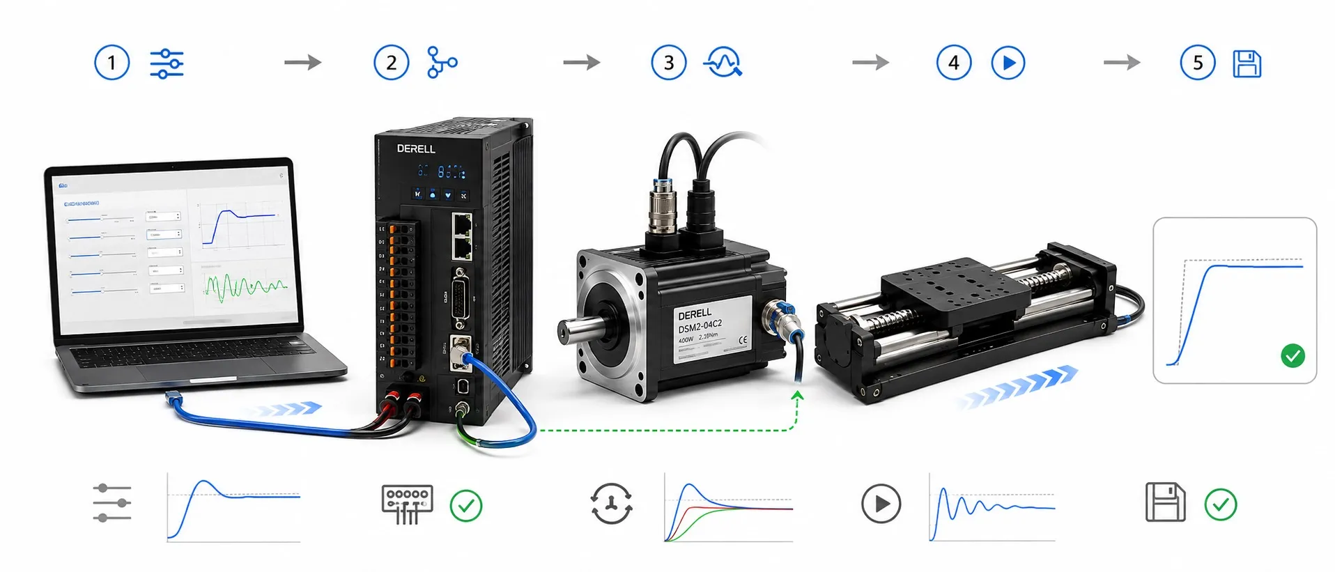
How Are Servo Drives Programmed and Configured?
Hello colleagues,
Programming and configuring a servo drive means identifying the correct motor, selecting the command source, scaling motion into machine units and tuning the control loops for the load. The servo drive and servo motor must be considered together. The PLC program, drive settings and mechanics must describe the same motion. A motor turning does not mean commissioning is complete.
1. Verify the motor and drive combination first
Check the motor model, supply voltage, rated and peak current, feedback interface and any holding brake. Motor-drive compatibility cannot be established from kW ratings alone. Power and feedback cables, connectors and the manufacturer's supported motor combinations must also match.
The coupling, gearbox, screw and load connections must be secure. For electrical checks and maintenance, follow the manufacturer's isolation, discharge-time and absence-of-voltage verification procedures. When changing an existing machine, back up the working parameters before making adjustments.
2. Identify the motor and configure its feedback
Some systems read motor data from an electronic nameplate; others require a motor code or manual entry of specified data. Set the motor type, current limits and feedback configuration using the manufacturer's procedure. Do not assume every drive requires power, speed and inertia values to be entered in the same way.
For an encoder or resolver, verify the interface, supply, cable and any required resolution setting. Incorrect commutation or feedback alignment can prevent proper torque production. Encoder bit resolution is not the number of command pulses sent by the PLC.
3. Choose position, velocity or torque control
Position mode moves an axis to a specified location or along a motion profile. Velocity mode follows a speed reference. Torque mode regulates torque demand in suitable applications. Choose between position control and speed and torque control according to the machine's task.
Establish where each control loop runs: a CNC or motion controller may close the position loop while the drive handles the remaining loops. Not all axes use the same architecture. In torque mode, consider speed and travel limits separately; a lightly resisted load can accelerate under applied torque.
4. Match the command source and I/O functions
Depending on the drive, commands may use pulse/direction, an analog reference, internal motion tables or an industrial network. With an EtherCAT servo, axis assignment, operating mode, data mapping and cycle settings must match the controller. A communication port does not imply support for every protocol or motion function.
Verify the meaning and active level of signals such as servo enable, ready, alarm and in-position. Enabling the drive and commanding motion are separate actions. A start request from an HMI must also work with the PLC's permissive and stop logic.
5. Configure electronic gearing and machine units
Electronic gearing defines the relationship between command counts and motor or load motion. The PLC's millimeters, degrees or revolutions must agree with drive scaling, gear ratio and the mechanical transmission. Before assessing positioning accuracy, establish that the commanded distance is correct.
Example: A directly driven screw has a lead of 5 mm per revolution, and the configured command interface accepts 10,000 pulses per motor revolution. This gives 2,000 pulses/mm, so a 100 mm move requires 200,000 pulses. The example assumes no gearbox and the stated command ratio; actual systems must include all transmission ratios. This count is neither encoder resolution nor guaranteed machine accuracy.
6. Verify direction, homing and travel limits
Make the initial move over a short distance at low speed. Check positive direction, physical motion and the position reported to the controller together. Correct direction using a manufacturer-supported method; randomly changing motor phases or feedback wiring is not an appropriate configuration procedure.
Homing establishes the machine coordinate reference. Depending on the method, it can use a reference sensor, encoder index or a defined current position. An absolute encoder does not automatically establish the correct machine zero. Verify hardware limits, software limits, homing direction and stopping distance for the application.
7. Distinguish protection from stopping functions
Assess current and torque limits against the capacity of the mechanics as well as the motor. Thermal management, overload monitoring and brake control are also part of configuration. An ordinary limit input or software travel limit is not, by itself, a certified safety function.
Where provided, STO safely prevents torque-producing energy from reaching the motor; it does not provide electrical isolation or mechanically hold the load. Controlled stopping, emergency stopping and holding a vertical load require separate consideration. Configure holding-brake release and engagement using the motor and drive manuals.
8. Tune the control loops for the actual load
On supported systems, auto-tuning can measure the load's behavior and propose gains and filters. Some tests move the axis automatically, so prepare the permitted travel area and the manufacturer's test conditions first. Resolve mechanical looseness, an engaged brake or incorrect scaling before starting automatic tuning.
Not every servo loop is adjusted through three PID gains. Common architectures use PI control for velocity and P control, or another manufacturer-defined structure, for position. During normal user setup, the current loop often uses predefined or automatic settings associated with motor identification; adjust it manually only when the manual requires this.
Higher gains can improve response, but excessive settings can produce oscillation, noise and overshoot. Evaluate filtering alongside dynamic performance. The target is stable, repeatable motion at the required accuracy, rather than the highest possible gain.
9. Test the motion profile with the real load
Set maximum speed, acceleration and deceleration within the machine's capability. Where supported, an S-curve or jerk limit can smooth transitions. Extremely short stopping times can exceed the capacity of the regenerative braking circuit and DC bus.
Begin with short controlled moves, then test the application's operating cycle. Monitor commanded and actual position, following error, current/torque, settling time and temperature. Also watch for maintenance-related symptoms, including cable strain, mechanical noise and loose connections. Simulation can help when available, but it does not replace measurements on the real machine.
10. Save the settings and document commissioning
Store verified settings using the drive's required nonvolatile save procedure; some devices initially retain changes only in working memory. Keep the parameter backup, PLC project, motor and drive models, software version and change description together. Following a planned restart, verify that settings, reference status and startup behavior are retained as intended.
Acceptance criteria extend beyond the absence of alarms. The axis must travel the correct distance in the correct direction, settle within the specified time, remain stable under load and demonstrate the defined stopping behavior. Explore the fundamentals in the Servo FAQ guide.