
optical encoder vs magnetic encoder?
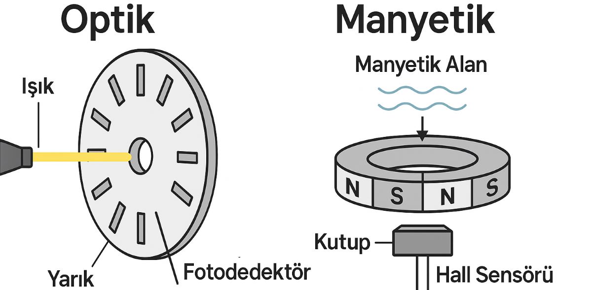
Optical or Magnetic Encoder: Which Should You Choose?
An optical encoder detects motion using light, while a magnetic encoder detects changes in a magnetic field. Both encoder technologies can provide position and speed feedback. Selection depends on accuracy, resolution, environmental conditions, mechanical construction and electrical compatibility together.
Applications include servo motor feedback, conveyors and positioning machines. These sensing methods are also used in linear encoders. There is no universal rule that optical encoders are cheaper or magnetic encoders are more accurate.
See the Sensing Principles in Motion
Optical code disk
Open region / opaque region
Magnetic pole ring
Blue: N • Red: S
Illustrative channel A — 50% duty cycle
12 complete periods / revolution
Pulse count:
Channel A frequency: Hz
The counter shows completed periods after the starting point. Reset returns the rotation and count to zero; select Start / Resume to move again. Counting pauses while the tab is in the background.
derell • ENC02
On the left, open and opaque optical regions pass the stationary reader. On the right, N–S pole regions move past a magnetic reader. Both illustrative models produce 12 complete periods per revolution for a fair visual comparison. Select 5, 10 or 20 RPM to change the rotation and reading indicators together. The diagram does not represent an actual product’s resolution, accuracy or maximum speed. The reading indicator represents changes in the region passing the reader.
How Does an Optical Encoder Work?
A common transmissive design combines an LED light source, a patterned code disk and a photodetector. As the disk rotates, open regions transmit light and opaque regions block it. Electronics process these changes into pulse signals or digital position information. Reflective designs also exist; not every optical encoder uses physical slots.
Optical systems are strong candidates where high resolution and high position accuracy are required. Dirt, oil or condensation in the optical path can affect some designs, while enclosed housings and advanced reading methods can reduce their impact. An optical encoder is not necessarily limited to a clean laboratory environment.
How Does a Magnetic Encoder Work?
Movement of a magnet, magnetised ring or suitable target changes the magnetic field seen by the reader. A sensor using the Hall effect or magnetoresistive sensing, together with processing electronics, derives position from these changes. The magnetic sensor’s primary role is to measure the field reaching it, rather than transmit a field towards the moving object.
Magnetic sensing can offer advantages when dirt or oil would obstruct an optical path. However, external magnetic fields, metal particles, magnet alignment and the reading gap can matter, depending on the design. Some models use a multipole ring, while others measure the angle of a single magnet. The visible number of poles alone does not determine final resolution.
Incremental and Absolute Describe a Different Feature
An incremental encoder reports changes as motion occurs; the starting reference is established according to the application. An absolute encoder provides a code identifying position within its measurement range. Optical or magnetic describes the sensing method, while incremental or absolute describes how position information is provided. Both sensing technologies are available in incremental and absolute forms.
Resolution Is Not the Same as Accuracy
Resolution describes the distinguishable position step. Accuracy describes how closely the reported position matches the true position. Repeatability describes the consistency of readings when returning to the same position. For example, 1000 complete signal periods per revolution on one channel correspond to 0.36° per period. That does not mean the encoder’s angular error is ±0.36°.
With quadrature outputs, x4 evaluation of the rising and falling edges can provide 4000 counts per revolution. A smaller counting step does not automatically improve measurement accuracy by a factor of four. Compare the manufacturer’s angular error, repeatability and specified operating conditions.
Electrical Limits at Higher Shaft Speeds
An encoder producing 1000 complete signal periods per revolution on one channel generates 1000 × 1500 / 60 = 25,000 Hz at 1500 RPM. With x4 decoding, the receiver may need to process 100,000 edges per second. The PLC or controller therefore needs a suitable high-speed counter input and correctly configured filtering. The optical or magnetic label does not guarantee that a controller can read the output.
Why Do the Interface and Installation Matter?
Encoder output types can include open collector, push-pull and differential interfaces. Match TTL/HTL levels, supply voltage and the receiver’s input circuitry. A suitable line driver output requires a compatible differential receiver. Matching wire colours or connectors do not prove electrical compatibility.
Shaft misalignment, coupling loads, bearing limits and, in magnetic designs, the reader-to-target gap can affect performance. Mechanical installation matters alongside noise suppression and signal filtering. Follow the manufacturer’s instructions for shielding, grounding and signal references; one wiring rule does not suit every system. The selected resolution of a programmable encoder must also remain within the receiver’s speed limits.
A Practical Comparison
| Criterion | Optical encoder | Magnetic encoder |
|---|---|---|
| Sensing | Light and a coded disk or scale. | A magnetic field and suitable reader. |
| Precision positioning | High-accuracy products are available; check specified errors. | Check product resolution, angular error and installation tolerances. |
| Contamination | Optical-path protection and dirt immunity matter. | Can resist optical contamination; assess field and particle effects. |
| Speed and interface | Check permitted shaft speed and output frequency. | Check permitted shaft speed and output frequency. |
| Cost | Construction, performance, interface and protection features determine cost; the sensing technology alone does not establish a price ranking. | |