
What is totem pole output?
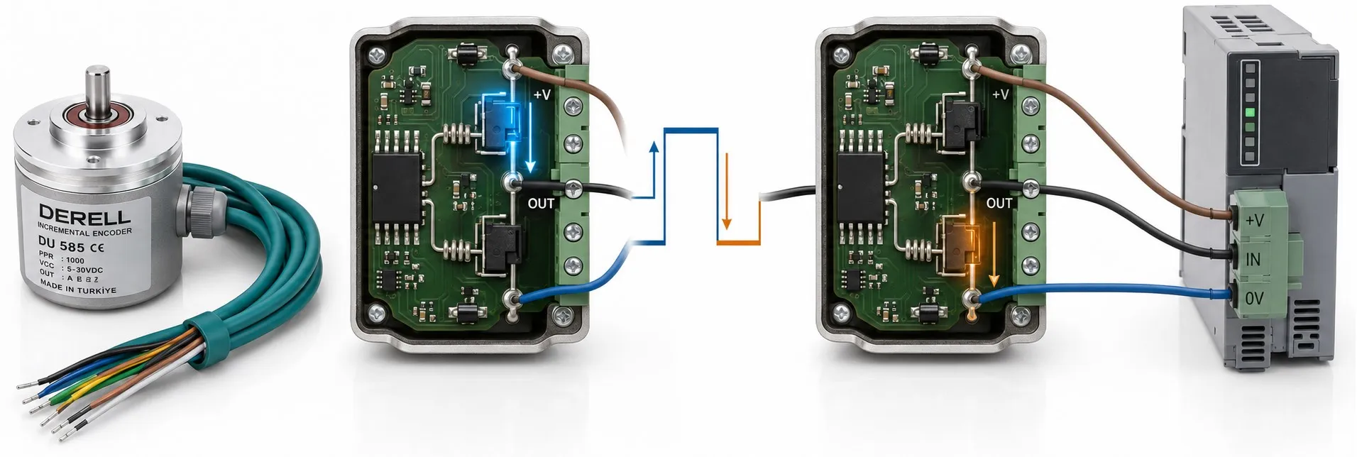
What is a totem-pole output? How push-pull driving works
A totem-pole output actively drives its signal terminal both HIGH and LOW. It appears in encoders and digital circuits. It is neither a communication protocol nor a voltage standard on its own. When comparing encoder output types, keep the output circuit and signal voltage as separate specifications.
The operating principle is an upper driver and a lower driver taking turns to control the output. This is the basis of push-pull driving. Classic TTL totem-pole stages use bipolar transistors; many modern outputs use MOSFETs. An actual circuit can contain more components than the two-switch model shown below.
Which path conducts in the HIGH and LOW states?
HIGH (1): The upper driver turns on and brings the output towards the positive drive rail; the lower driver is off. The output can source current when a load requires it. LOW (0): The lower driver turns on and brings the output towards the 0 V rail; the upper driver is off. The output can then sink current. The load determines the current; a HIGH output does not necessarily mean continuous current is flowing.
The NPN and PNP output comparison helps explain sourcing and sinking. However, labelling a totem-pole output simply NPN or PNP is insufficient: its defining feature is actively driving both levels. If both drivers conduct strongly at the same time, they can create unwanted short-circuit current between the supply rails.
How does it differ from an open-collector output?
An NPN open-collector or N-channel open-drain output actively drives LOW and becomes high impedance when switched off. HIGH is usually established by an external or input-integrated pull-up resistor. A totem-pole output actively drives HIGH as well, so it normally needs no pull-up just to generate HIGH. PNP open-collector arrangements have a different current direction.
Active driving can give sharper transitions, especially with capacitive loads. However, low output impedance does not mean unlimited current or a perfect signal on every cable. An open-collector rising edge depends on the pull-up and capacitance; a totem-pole transition depends on driver capability and loading.
Are totem-pole, TTL, HTL and differential the same thing?
No. Totem-pole/push-pull describes how the output is driven, while TTL and HTL describe electrical signal classes in encoder applications. Push-pull outputs can be found in both 5 V class and 24 V applications. Check output voltage and supply voltage separately in the model's data sheet.
A differential output is another property: information is read from the difference between two lines such as A+/A−. A line-driver encoder or RS-422 interface can use active output drivers internally. The push-pull label alone does not guarantee differential transmission.
Simulation: which switch is driving the output?
Select HIGH or LOW and watch the active switch, conducting path and latest waveform sample together. Start alternates slowly between the two states.
| Output | Upper switch | Lower switch |
|---|---|---|
| HIGH (1) | ON | OFF |
| LOW (0) | OFF | ON |
ON
OFF
Ideal output logic history
Output: HIGH (1) · 5 V
The upper switch connects the output to the supply rail and can source current into a load.
A manual selection pauses automatic playback and holds the selected output state. The chart shows the last 16 logic samples at the selected voltage on the same 0–24 V scale.
This is a two-switch functional model, not an actual transistor wiring diagram. It does not calculate voltage drops, load current, noise or switching time. Both switches are not commanded on together in normal operation. Showing an active switch does not imply continuous current when there is no load current.
What should you check before connecting a PLC input?
Check the PLC or drive's input voltage, HIGH/LOW thresholds, input current and single-ended/differential arrangement. Do not connect a 24 V output directly to a 5 V input. Encoder pulses require a suitable high-speed counter or encoder module. When choosing a cable and connector, also match the pin assignment, signal reference and shield connection.
Why does the output current rating matter?
Example: imagine a 24 V output driving a 1 kΩ resistive load connected to 0 V while HIGH. The ideal current is I = V / R = 24 mA. If the driver's limit is 20 mA, this load exceeds it. This is only a calculation example; it does not mean a PLC input necessarily has a resistance of 1 kΩ. Check the per-channel current limit, actual HIGH/LOW voltages and short-circuit protection conditions in the data sheet.
Does it increase an encoder's speed or resolution?
Totem-pole describes how an incremental encoder drives its electrical signal; it does not automatically increase PPR. For example, a 600 pulse-per-revolution encoder at 3000 RPM produces 600 × 3000 / 60 = 30,000 Hz on one channel. The output and receiver must support the required counting frequency. Long-cable capacitance and input filtering can reduce the benefit of a fast driver.
Can two totem-pole outputs be connected together?
Do not connect them directly unless the manufacturer explicitly permits it. If one drives HIGH while the other drives LOW, the outputs oppose each other and may cause excessive current or damage. Encoder channels A and B must not be combined this way either. Use suitable logic, buffers or signal distributors to combine or distribute signals. Shared-line arrangements that can work with open-collector outputs cannot automatically be applied to push-pull outputs.
Technical references: Texas Instruments output circuit explanation · Hengstler push-pull encoder outputs.