
what is Hollow shaft encoder?
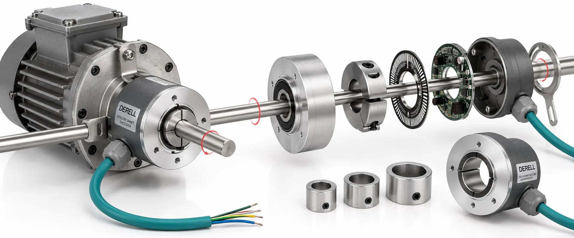
A hollow-shaft encoder is a rotary encoder whose rotating hub fits over a machine shaft. The opening belongs to the encoder; the machine shaft itself can be solid. The hub turns with the shaft while a suitable support keeps the encoder housing from rotating.
“Hollow shaft” specifies the mechanical connection. It does not specify the sensing technology or output. The device can be incremental or absolute, and may use an optical or magnetic measuring principle.
Three shaft arrangements to recognise
A blind hollow shaft accepts the machine shaft into a bore that does not pass completely through the encoder. Check the required engagement length, available bore depth and specified clearance. A shaft touching the bottom of the bore does not establish a correctly secured connection.
A through hollow shaft, also called a through-bore arrangement, lets a suitable machine shaft pass through the encoder. A standard one-piece assembly still normally needs access from a shaft end. The opening does not make it a split device that can simply be fitted sideways around an installed shaft.
A solid-shaft encoder has its own projecting shaft. It commonly connects to the machine shaft through a separate coupling. Hollow-shaft mounting can remove that intermediate coupling, but compatible mounting accessories may still be needed. It changes the mechanical arrangement rather than eliminating every mounting component.
Two connections do different jobs
The rotating hub needs a secure connection to the machine shaft. The housing needs a torque arm or an appropriate stator coupling to prevent rotation. Many designs allow specified small movements so the assembly does not impose unwanted loads on its bearings. The encoder measures rotation relative to its housing; an uncontrolled housing movement corrupts that relationship.
A torque arm does not measure torque. It is a mechanical restraint. A conventional encoder reports position, from which speed can be calculated. In a servo feedback system, a drive's current-based torque estimate is a different quantity from a direct shaft-torque measurement.
Check the fit before tightening anything
Start with shaft diameter, diameter tolerance, available engagement length, surface condition and runout. Two encoders described as having a 12 mm bore may have different requirements. Use a reducing insert only where the manufacturer approves it; improvised packing material is not a reliable way to correct an unsuitable fit.
Clamping rings and set screws must be installed according to the model's instructions. There is no universal tightening torque or shaft tolerance for every hollow-shaft encoder. Install with the machine stopped and unexpected movement prevented. Do not hammer the encoder onto the shaft, and leave room for the connector, cable bend and later removal.
The encoder's bearings should not be treated as additional support bearings for the machine. Shaft runout and incorrect restraint can create mechanical loading and angular errors. An IP protection rating is separate from the permitted rotational speed, temperature, vibration and shaft movement.
Hollow shaft and multiturn describe different things
Hollow shaft describes how the device connects to a shaft. Singleturn describes absolute position within one revolution; multiturn includes revolution information. A multiturn device does not have to be a multichannel device. Linear encoders form a separate measuring family, so they should not be listed as a subtype of hollow-shaft rotary encoder.
Rotation can be converted into linear travel using a screw or drum, but the calculation needs the correct screw lead or transmission ratio. Backlash and other mechanical errors remain relevant. A linear sensor or draw-wire encoder measures at a different point in the mechanism. Motor rotation alone cannot establish actual load movement under every condition.
A 1024 PPR example: Speed, counts and angle
Assume channel A produces 1024 pulses per revolution and the shaft turns at 1500 rpm. The channel frequency is 1024 × 1500 / 60 = 25,600 Hz. Counting every edge on both A and B with ×4 decoding produces 102,400 counts per second. The nominal angular increment becomes 360 / 4096 ≈ 0.0879°; this is a resolution calculation, not an accuracy guarantee.
A PLC needs a suitable high-speed counter and the correct decoding setting. Check how its manual defines the maximum counting frequency, and how the encoder maker uses PPR and CPR. A wrong scaling factor can also produce incorrect readings on counters and tachometers, even when the mechanical installation is sound.
Electrical compatibility matters just as much
Match the encoder output signal to the receiving electronics. HTL, TTL and line-driver outputs are not interchangeable connections. A differential RS-422 signal needs a compatible receiver. Absolute devices may use SSI, CANopen or another interface. Matching the shaft diameter does not make an encoder compatible with a drive designed for a resolver.
When replacing a motor's feedback device, check the protocol, pin assignment, supply, direction convention and, where required, the commutation relationship. Choose optical or magnetic sensing from the actual accuracy and environmental specifications. Neither technology guarantees the better result in every application.
Hollow-shaft does not mean bearingless. Separate ring-and-readhead arrangements are a different mechanical design. Temperature or condition-monitoring data are also model-dependent features. A successful selection balances the measuring task, mechanical fit, electrical interface and maintenance access.