
Resolver vs encoder?
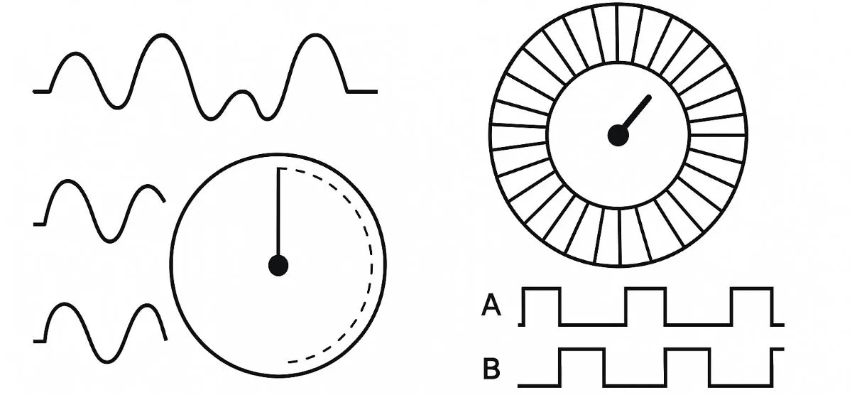
Resolver vs encoder: operation, accuracy and interface differences
Hello everyone. Resolvers and encoders provide shaft-position feedback to a control system. Selection depends on required accuracy, position availability at startup, operating conditions and the drive interface. Claims such as “a resolver is always tougher” or “an encoder is always more accurate” are too broad to guide a reliable selection.
The central distinction is that a resolver carries angle information in excited winding outputs, while encoders form a broad family of sensing and output technologies. First distinguish incremental, absolute and analogue sin/cos designs.
Quick comparison: the same position, different information
| Feature | Resolver | Incremental encoder | Absolute encoder |
|---|---|---|---|
| Basic information | Electrical angle from sin/cos signals | Movement and direction relative to a reference | Position code within a defined measuring range |
| Typical connection | Excitation + SIN/COS pairs; compatible resolver input/RDC | A/B; depending on model, Z, complementary channels or analogue sin/cos | Compatible serial, parallel or other position interface |
| Position at startup | Angle within a turn for one pole pair; no inherent previous-turn count | A reference is needed to relate counting to machine position | Singleturn or multiturn information depends on the product |
| Digital resolution | Determined by the resolver and conversion chain | Determined by PPR, evaluation factor and any interpolation | Determined by position bits and measuring design |
| Selection criterion | Evaluate total measurement error, dynamic behaviour, environmental limits and interface compatibility together. | ||
How does a resolver signal become angle information?
A resolver uses electromagnetic coupling. With suitable AC excitation, its two output amplitudes depend on the sine and cosine of shaft angle. An ideal one-pole-pair model can be written as Vsin = K × sin(θ) × sin(ωt) and Vcos = K × cos(θ) × sin(ωt). K combines excitation amplitude and transformation ratio.
These outputs are not directly DC angle voltages. A drive with a compatible resolver input or a resolver-to-digital converter (RDC) processes the carrier to obtain angle. The model below uses normalised, demodulated values and atan2(sin, cos). A real RDC tracking loop is more involved than this mathematical illustration. With multiple pole pairs, electrical angle repeats within one mechanical revolution; the resolver pole count must match the drive configuration.
Do all encoders produce A/B square waves?
No. Common incremental A/B outputs have a 90-electrical-degree phase displacement: edge order indicates direction and the pulse count represents movement. Absolute encoders transmit coded position values. Analogue encoders can provide sin/cos signals for interpolation. An analogue sin/cos encoder and a resolver must not be assumed to use the same excitation or input circuitry.
The sensing principle and output interface are separate specifications. Optical, magnetic/Hall-effect or capacitive sensing does not, by itself, identify an encoder as incremental or absolute. This explains why two mechanically similar sensors can require different feedback cards.
Why distinguish resolution, accuracy and repeatability?
Resolution is the smallest distinguishable step; accuracy describes closeness to the actual position; repeatability describes returning to the same result under the same conditions. A 16-bit angle code has an ideal step of 360° / 65,536 ≈ 0.00549°. This does not establish measurement accuracy of ±0.00549°.
A 1024 PPR A/B encoder, evaluated correctly at x4, gives 4096 counts per turn and a nominal 0.08789° step. This counts rising and falling edges on both channels; it does not create additional physical graduations. Installation eccentricity, signal errors and mechanical backlash remain separate concerns. Likewise, RDC bit depth alone does not describe resolver-system accuracy: sensor and converter errors must be considered together.
Simulation: one shaft, three kinds of position information
Change the angle and compare resolver sin/cos amplitudes, incremental A/B states and the absolute encoder code. Then restart the controller to explore the reference difference.
Basic example: 0° → sin = 0, cos = +1; 90° → sin = +1, cos = 0. An incremental encoder counts movement; an absolute encoder provides a position code.
sin(θ) = 0.000
cos(θ) = 1.000
atan2 → 0.0000°
A = 0 · B = 0
Relative count: 0
Angle represented by count: 0.0000°
Digital step: 5.625000°
Position code: 0 / 4095
Displayed information: 0.0000°
Digital step: 0.087891°
Reference status: 0° reference established
Resolver: four excitation cycles at the selected angle
Incremental encoder: A/B levels versus angle
The resolver plot shows normalised AC outputs: the same carrier scaled by sin(θ) and cos(θ). The amplitude values above are after demodulation. The A/B plot is not a time history: its centre line marks the current angle and its horizontal span covers two electrical periods. In the positive direction, A leads B by 90 electrical degrees.
Try this: select 45°, press “Restart controller”, then select 60°. The resolver and absolute encoder show angle within the turn; the incremental counter measures only movement since the restart. Changing PPR also restarts the relative counter.
The model uses a one-pole-pair resolver, ideal x4 incremental counting and a singleturn absolute encoder. Each absolute code is converted to the lower boundary of its interval. Resolver angle uses ideal atan2 calculation; RDC quantisation, measurement error, noise and communication latency are excluded. “Move to 0° and reference” moves the virtual shaft to a known origin; it does not replace actual machine homing or commutation setup.
What happens after a power interruption?
A one-pole-pair resolver can determine the current angle within a turn once excitation and reading resume; it does not inherently retain the number of completed turns. Even if an incremental counter value is stored, movement while power is off may go unrecorded. A Z index pulse can support a revolution reference; it cannot alone determine a multiturn machine position.
A singleturn absolute encoder provides position within a turn; a multiturn absolute encoder also provides turn information within its specified range. Tracking movement without power, and any battery requirement, depend on the technology. An absolute reading does not automatically establish the correct machine datum or motor commutation offset.
Can it connect directly to a PLC or servo drive?
A standard digital input on a PLC cannot read every feedback type. Incremental pulses require a compatible high-speed counter or encoder module; a resolver requires an appropriate resolver input and excitation circuit; an absolute encoder requires its supported protocol. Match output type, TTL/HTL levels and differential signalling separately. Line-driver and EnDat describe different aspects of an interface.
Frequency example: At 3000 RPM, a 1024 PPR encoder produces 51.2 kHz of pulse periods per channel; x4 evaluation processes 204,800 edges/s in total. Check how the receiver defines its counting frequency, along with input filtering and cable limits. Cable/connector pin assignments, shielding and the manufacturer's termination instructions are part of compatibility too.
Which handles temperature, vibration and maintenance better?
Suitably designed resolvers are strong candidates for high temperatures and demanding industrial environments. However, assess IP protection, temperature range, vibration/shock limits and electromagnetic compatibility for each product. Sealed optical or magnetic encoders can also suit harsh conditions. Analogue does not mean immune to interference, and optical sensing does not inherently mean rapid mechanical wear.
Contactless sensing does not make the entire assembly free of wear: bearings, seals and mounting parts still matter where fitted. Suitable encoder couplings and mounting arrangements help limit bearing loads caused by misalignment. Mechanical options such as hollow-shaft encoders should also match the installation.
How should the application guide selection?
Speed and quantity tracking: An incremental encoder with a compatible counter can be practical when referencing is manageable. Position required at startup: Consider an absolute encoder with the correct singleturn/multiturn coverage. Motor drive with resolver input: Use a resolver approved for that motor and drive combination. High-accuracy axis: Assess installed measurement error and the mechanical transmission together.
Motor position does not always represent load position with the same accuracy. Where gearbox backlash or a screw transmission dominates, measurement at the load, a suitable linear encoder or a second feedback device may be needed. Include the feedback card/RDC, cabling, mounting and commissioning in cost comparisons rather than considering sensor price alone.
Two common questions
Can an encoder replace a resolver? Only when the drive supports the new feedback and the mechanical fit, interface, direction, motor identification and commutation settings can be configured correctly. An adapter with the same connector is insufficient.
Does an analogue resolver have unlimited resolution? Its output can vary continuously, but usable position information is limited by noise, accuracy, converter resolution and dynamic response. A continuous signal does not provide infinite measurement precision.
Technical sources: Analog Devices — resolvers/RDCs · Analog Devices — RDC interface example · HEIDENHAIN — encoder interfaces · Renishaw — rotary measurement accuracy · TI — industrial resolver feedback.