
Callendar–Van Dusen Equation and Pt100 Conversion
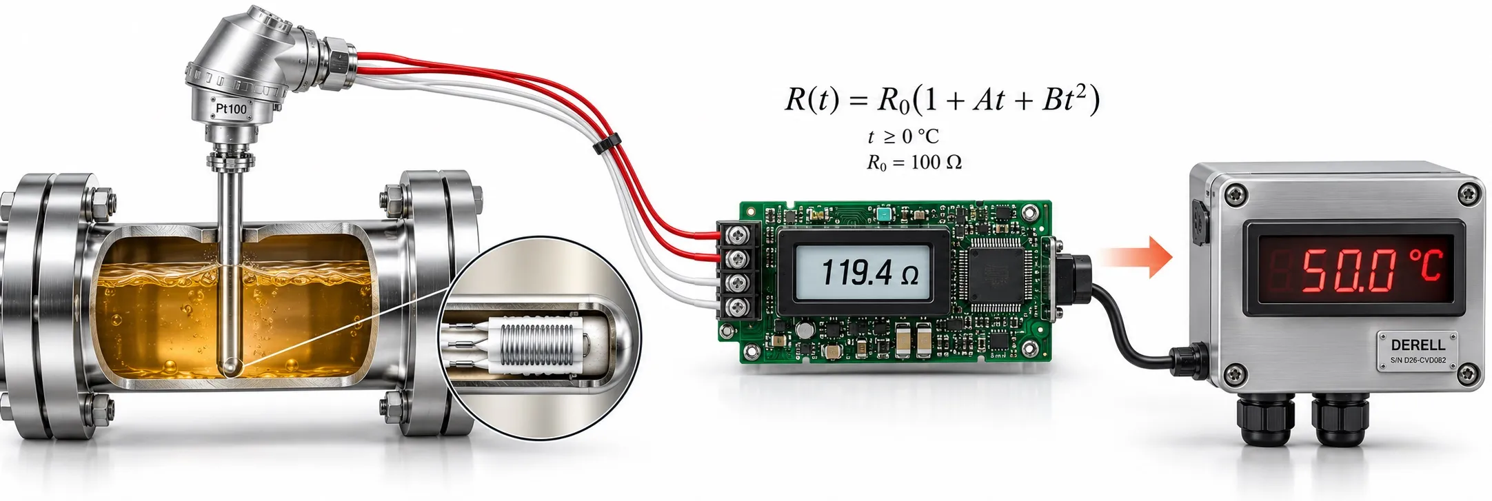
Callendar–Van Dusen Equation and Pt100 Conversion
The Callendar–Van Dusen equation describes the relationship between resistance and temperature in a platinum temperature sensor. A Pt100 sensor has a nominal resistance of 100 Ω at 0 °C. Its resistance rises as temperature increases, but the change per degree is not exactly constant. The equation accounts for this curvature.
The reference relationship for industrial platinum sensors is covered by IEC 60751. See industrial temperature measurement standards for the broader context. This explanation concerns the common platinum RTD characteristic with α ≈ 0.00385; the same coefficients cannot be applied to every resistive temperature sensor.
Why convert resistance into temperature?
The sensor presents an electrical resistance that depends on temperature. A measurement circuit applies a known current and measures voltage. Ohm’s law gives R = V / I, and the appropriate sensor curve converts resistance into temperature. Accurate resistance measurement and correct curve selection are separate requirements.
Equation and coefficients
Nominal curve from 0 °C to 850 °C:
R(t) = R₀ × [1 + A × t + B × t²]
Nominal curve from −200 °C to below 0 °C:
R(t) = R₀ × [1 + A × t + B × t² + C × (t − 100) × t³]
t is the numerical temperature in °C, R(t) is resistance at that temperature, and R₀ is resistance at 0 °C. Nominal R₀ is 100 Ω for Pt100 and 1000 Ω for Pt1000. The common coefficients are:
A = 3.9083 × 10⁻³ °C⁻¹
B = −5.775 × 10⁻⁷ °C⁻²
C = −4.183 × 10⁻¹² °C⁻⁴
Keep the negative signs of B and C. The term containing C is used only below zero. α describes the average temperature coefficient from 0 to 100 °C and is not equal to A. The −200…850 °C model range does not establish the operating range of every probe. Check probe construction, metal-sheathed platinum thermometer requirements and the applicable Pt100/Pt1000 tolerance class against the product specifications.
Example values for Pt100 and Pt1000
| Temperature (°C) | Pt100 (Ω) | Pt1000 (Ω) |
|---|---|---|
| -100 | 60.2558 | 602.5584 |
| 0 | 100.0000 | 1000.0000 |
| 100 | 138.5055 | 1385.0550 |
| 200 | 175.8560 | 1758.5600 |
| 500 | 280.9775 | 2809.7750 |
With the same coefficients, nominal Pt1000 resistance is ten times Pt100 resistance. The displayed decimal places do not guarantee measurement accuracy. Actual sensor tolerance, calibration and the measurement circuit affect the result.
How do you convert resistance into temperature?
At zero and above, the quadratic equation can be inverted:
t = [−A + √(A² − 4 × B × (1 − R / R₀))] / (2 × B)
This expression applies to the 0…850 °C branch of the nominal curve above. For example, R₀ = 100 Ω and R = 125 Ω give approximately 64.58 °C.
Below zero, the C term is also present, so the same inverse formula does not apply. Use numerical root finding within the valid range, or interpolation in a validated resistance–temperature table. Software should check that the reading is within range before selecting the correct temperature branch.
Why is the 0.385 Ω/°C approximation limited?
For Pt100, t ≈ (R − 100) / 0.385 is a convenient linear approximation. However, 0.385 Ω/°C is not the exact slope at every temperature. The nominal resistance at 200 °C is 175.856 Ω. The linear calculation returns approximately 197.03 °C, about 2.97 °C lower. Conversion over a broad range needs to account for curvature.
Lead resistance and sensor self-heating
Two-, three- and four-wire RTD connections respond differently to lead resistance. In a two-wire measurement, the combined resistance of both leads adds to the sensor resistance. A total extra lead resistance of 1 Ω can cause a reading about 2.6 °C too high near zero. Three-wire compensation depends on matched leads and the circuit method. Four-wire measurement separates current and voltage paths to reduce lead effects.
Self-heating and lead resistance errors remain relevant even with a correct equation. Sensor power is P = I² × R. At 100 Ω, a current of 1 mA produces 0.1 mW, while 5 mA produces 2.5 mW. Power increases by a factor of 25; the temperature rise depends on probe construction and heat removal by the surrounding medium.
Correct use in a PLC or controller
First identify the available data: raw ADC counts, resistance or converted temperature. Raw counts are not directly ohms. If an RTD module already calculates temperature, do not apply a second Callendar–Van Dusen conversion. For an analog signal, check the analog input type and scaling. A standard 0–10 V or 4–20 mA input cannot directly measure Pt100 without suitable RTD measurement hardware or a transmitter.
For analog controllers, select compatible sensor type, coefficients, R₀ and wiring. If calibration provides individual sensor coefficients, distinguish them from nominal values. An open or shorted sensor reading must not be passed to PID control as a valid temperature. The difference between a temperature sensor and a thermostat also helps explain measurement and switching functions.
Does the equation apply to other temperature sensors?
Pt100 sensors and thermocouples measure different physical quantities. Thermocouple conversion uses IEC 60584-1 reference functions and thermocouple tables and ITS-90. For NTC and PTC sensors, use the relevant material and manufacturer characteristic. Pt100 coefficients are not a universal temperature formula.
Editor’s note: This page explains nominal platinum RTD conversion. The accuracy of a calculated temperature must be assessed together with sensor tolerance, actual R₀, calibration, wiring, excitation current and electronic circuit errors. Consult the sensor and instrument documentation when selecting coefficients and the usable temperature range.
Related topics and products
What is Pt100? · IEC 60751 · Tolerance classes · RTD connections · Custom Pt100 sensors
External reference links
The publications below explain the equation, the scope of the standard and measurement circuits. Table values were calculated using the coefficients stated on this page.
IEC 60751:2022 — Industrial platinum resistance thermometers and platinum temperature sensors
NI — Resistance Temperature Detectors (RTDs)
Analog Devices — RTD Measurement System Design Essentials
Analog Devices — Choosing and designing an RTD sensing system