
Smart Fuses
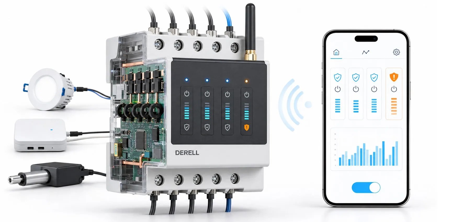
The term smart fuses describes products that combine circuit protection with measurement, status reporting and control. “Smart” does not describe a single operating principle. One device may electronically limit current, while another communicates the state of a conventional circuit breaker. When assessing a fuse or protective device, identify what it protects, what causes it to operate and which information it provides.
This group can include board-level eFuse solutions, DIN-rail electronic protection modules and circuit breakers fitted with communication accessories. An eFuse combines protection functions within an integrated circuit; another system may use separate components for measurement, switching and communication. Load switching can also involve relays. Similar appearance or the word “smart” does not make these products interchangeable.
How is current monitored and the circuit protected?
An electronic protection device uses information about load current in its trip or current-limiting circuitry. The load remains supplied within the normal operating limits. During an overload or short circuit, the design determines whether the device limits current, switches off its output or trips after a specified delay. Products respond differently, so their protective behaviour cannot be established from the ampere rating alone.
Devices with electronic switching can use semiconductor components such as a MOSFET. Switching off this output is physically different from melting the element in a conventional fuse. Some devices limit current during a fault; others keep the output switched off. This distinction matters when considering the load's fault withstand time, the power supply's response and required upstream protection. Read the model's trip characteristics together with its specified operating conditions.
Monitoring, communication and remote control
Monitoring means receiving information; control means instructing a device to perform an action. Being able to read current does not establish that the device can be switched remotely. Likewise, remotely switching a channel does not establish that the device measures energy consumption. Compare current, voltage, power, energy, channel status and event logging as individual product capabilities.
Models using industrial communication may provide interfaces such as IO-Link, Modbus or Ethernet; others may use a wireless connection. These options are not present on every device. A protocol name alone is insufficient to establish compatibility: the required master or gateway, supported data and commands, and compatibility with the control software also matter. Check the manufacturer's documentation for the behaviour of local protection and outputs if communication is lost.
What does a reset do after a fault?
A reset does not repair a fault. It allows an output that has been switched off by protection to be re-enabled. Some devices use a local button; others accept an external signal or a communication command. Models with automatic retry may attempt to restore power under defined conditions. The availability and configuration of this behaviour depend on the model.
Restoring power must be considered alongside the load's function. Re-energising a sensor supply and re-energising a machine circuit capable of producing movement can have different consequences. Also, a fault indication is not a definitive diagnosis. An overcurrent or undervoltage message helps direct an investigation; it does not establish that a problem in the wiring, connections or load has been resolved.
What can it offer in industrial applications?
In multi-channel DC distribution, one objective is to identify a faulty sensor or auxiliary circuit branch while allowing other branches to continue operating. Channel status and current information can help show which branch needs investigation. However, disconnecting only the faulty branch depends on coordination between the power supply, wiring, loads and protective devices. Remote monitoring provides useful maintenance information; it does not by itself repair faults or guarantee uninterrupted operation.
Which information is needed to select a product?
Start protective-device selection with the AC/DC operating voltage, normal load current and number of poles or channels. Then assess start-up current, capacitive loads, trip time and the total supply current for multi-channel devices. Short-circuit breaking capacity is important for a mains circuit breaker. For an electronic module, consider the manufacturer's fault-current limits, current-limiting behaviour and upstream protection requirements. Ratings belonging to one device family must not simply be applied to another.
Match the communication interface, adjustable protection thresholds, remote commands and reset behaviour to the application. For installation, check DIN-rail or board mounting, conductor size, device dimensions and ambient temperature. An adjustable product is not automatically suitable for every load. A model that provides the required functions within the application's electrical limits is the appropriate starting point.
Browse the main fuse category for products. If a suitable option is not listed, send the seller identified in the relevant product listing your AC/DC voltage, normal and start-up currents, pole or channel count, communication interface and reset requirements. Assess pricing, availability, delivery and sales conditions for the particular product.