
What types of Ethernet cables are there?
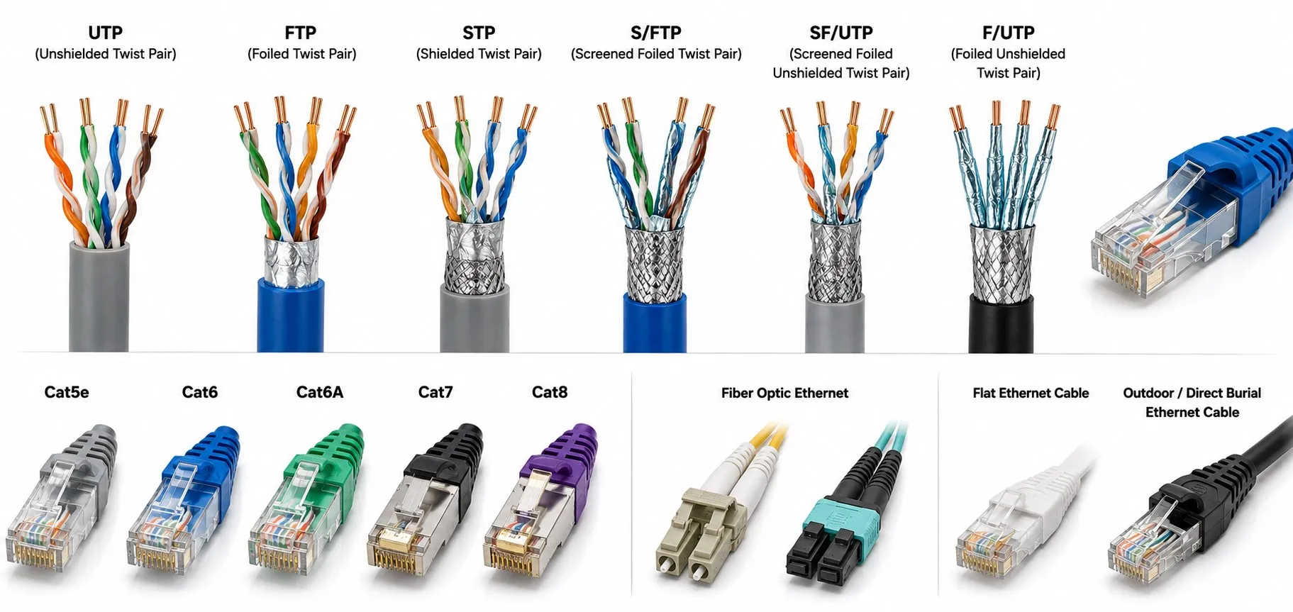
Illustrative image, not a cable cross-section, pinout or device-compatibility diagram.
What types of Ethernet cables are there?
Categories · Shielding · Motion and jackets · Fiber · Selection examples · Testing
Ethernet cable types are not just a ladder from Cat5e to Cat8. Start with the transmission medium—twisted-pair copper or optical fiber—then specify electrical performance, shielding, conductor construction, connectors and mechanical duty. Cat6A, S/FTP and RJ45 describe different things. One cable assembly can carry all three descriptions. Understanding that distinction is more useful than buying the highest number on the shelf; it also fits the wider Ethernet architecture. [1] [7] [9]
A simple way to picture it: the category describes the performance the route is built to support, the connectors are its entrances, and the jacket protects it from the surroundings. A faster-rated route does not make a slow entrance faster. Before choosing a cable, ask what the two ports need, how far apart they are and what the cable will experience between them.
Copper categories: Cat5e through Cat8
A category specifies electrical cabling performance over a frequency range; MHz is not a data rate in Mbit/s. The actual Ethernet link speed also depends on the PHYs at both ends and the completed channel. A channel includes the relevant connecting hardware and cords, not merely the bulk cable printed with a category number. [1] [6]
On a narrow screen, scroll the table sideways within its own area.
| Category | Bandwidth | Common application / channel reach | Qualification |
|---|---|---|---|
| Cat5e | 100 MHz | 1000BASE-T: 1 Gbit/s over 100 m | Also supports 2.5GBASE-T on a suitable channel. [1] [2] |
| Cat6 | 250 MHz | 1 Gbit/s over 100 m; shorter reach for 10GBASE-T | 10 Gbit/s at 55 m or less is conditional, not a 100 m promise. [1] |
| Cat6A | 500 MHz | 10GBASE-T: 10 Gbit/s over 100 m | Requires a compliant complete channel. [1] |
| Cat7 / Cat7A | 600 / 1000 MHz | 10 Gbit/s over a suitable 100 m Class F / FA channel | ISO/IEC categories; connector system and TIA distinctions matter. [3] |
| Cat8 | 2000 MHz | 25GBASE-T / 40GBASE-T over 30 m | A short, two-connection channel—not 40 Gbit/s over 100 m. [4] |
“Cat5e stops at Gigabit” is too simplistic. 2.5GBASE-T supports suitable Cat5e channels up to 100 m; Cat6 is the baseline cabling choice for 5GBASE-T. Certain installed Cat5e channels can support 5 Gbit/s under the relevant extended-frequency conditions, but that is a qualification question, not a blanket promise. Both the network interface and the switch port must support the chosen rate. [2]
Do not treat 55 m as an unconditional Cat6 guarantee for 10GBASE-T. Alien crosstalk from nearby cables and the installed channel affect the result. For a new 100 m 10GBASE-T channel, Cat6A is the defined option rather than an attempt to stretch the shorter Cat6 case. [1]
Cat7A does not provide a general IEEE guarantee of 40 Gbit/s over 50 m. Cat7 and Cat7A belong to ISO/IEC cabling, associated with Class F and Class FA; TIA does not recognize that same category sequence. GG45 and TERA connectivity are part of the distinction. Terminating Cat7 bulk cable with ordinary RJ45 plugs does not establish a Class F/FA channel. The standardized short copper channel for 25/40GBASE-T belongs to the Cat8 family. [3] [4]
Cat3 and original Cat5 mostly arise when assessing legacy installations. Do not read an old Cat5 marking as Cat5e; assess the installed link for the intended application. Coaxial 10BASE2 and 10BASE5 belong to Ethernet’s history, rather than the twisted-pair connection used between a modern controller and switch. [1]
Two pairs, four pairs, patch cords and crossover cables
100BASE-TX uses two data pairs; 1000BASE-T needs four. Four-core industrial cables therefore make sense in conventional 100 Mbit/s EtherCAT installations. They are not substitutes for an eight-core Gigabit Ethernet channel. An “EtherCAT cable” description should not be extended automatically to every EtherCAT variant, connector or power arrangement. [5] [6]
Patch cord describes a connection assembly, usually supplied with connectors; it is not an electrical category. Straight-through and crossover describe the wiring relationship between its ends. Ports with Auto-MDI-X or AutoCrossing can accommodate the appropriate pair routing automatically, while older or specialized equipment may require a particular arrangement. A factory-terminated cord is not automatically a continuous-flex industrial cord. [5] [11]
What the familiar 100 m limit actually includes
A common structured-cabling arrangement is a 90 m permanent link plus 10 m of patch and equipment cords. That allowance is not independent of cord gauge, insertion loss and temperature. Check the maximum cable length for the complete channel. A passive coupler does not regenerate the signal. Adding an active Ethernet switch creates separate links, but also adds a powered network component with its own environmental, maintenance and reliability requirements. [6] [17]
How to read U/UTP, F/UTP, U/FTP, S/FTP and SF/UTP
The letters before the slash describe the overall screen; those after it describe the pairs. U means unscreened, F foil, S braid and TP twisted pair. U/UTP has neither overall nor pair screens. F/UTP has an overall foil. U/FTP has individually foiled pairs. S/FTP combines an overall braid with pair foils. SF/UTP combines overall braid and foil without individually screened pairs. “STP” alone is too vague to specify the construction. [6] [11] [19]
Near servo equipment and switched power circuits, screening is one part of the EMC design—not a cure that works independently of installation. The connector and screen contact need to preserve the intended shielding path. A long, thin screen pigtail is not equivalent to a broad, low-impedance termination at high frequencies; routing still matters. [7]
“Always connect the shield at one end only” is not a universal Ethernet rule. Follow the equipment’s screen-termination and equipotential-bonding design. A cable screen is not a protective-earth or bonding conductor. Where a potential difference exists, review the installation rather than improvising by cutting the screen. [6] [7]
RJ45 and M12: connector shape is not protocol support
RJ45 does not tell you which industrial protocol a port supports. PROFINET, EtherNet/IP and other protocols carried over Ethernet depend on the equipment. Neither a green jacket nor a plug that physically fits proves compatibility. A cable cannot add a protocol implementation that the controller or field device does not have. [5] [9]
Four-contact, D-coded M12 connectors are common for 100 Mbit/s connections. Manufacturers also offer eight-contact, X-coded M12 Cat6A assemblies rated for rates up to 10 Gbit/s. “M12” or “eight pins” alone is insufficient: coding, pin assignment and the product specification must match. Ingress ratings such as IP65/IP67 apply under the stated conditions, commonly with the connection correctly mated. [8] [9]
Conductor construction, jackets and continuous movement
Solid and stranded describe conductor construction, not conductor material. All-copper cables can be solid or stranded. Stranding improves flexibility, but it does not by itself establish continuous-flex life. An AWG 23/1 designation, for example, describes a solid conductor; an assembly intended to move repeatedly requires additional mechanical qualifications. [10] [19]
Fixed installation, occasional flexing, cable-chain travel and robotic torsion are separate duties. On an industrial robot, check the required twist, bend radius, temperature and cycle conditions rather than accepting “flexible” as a complete specification. A manufacturer’s cable-chain test applies to that product under its stated conditions; it is not a transferable guarantee for another cable or a different motion profile. [10] [11]
PVC, PUR and LSZH do not provide a complete environmental specification. An oil-resistant PUR product does not prove that every PUR compound resists every coolant or cleaning chemical. Check outdoor exposure, UV, washdown, chemical compatibility and fire-performance requirements separately. The connector must also suit the conductor dimensions, cable diameter and solid or stranded construction. [11] [17]
Copper-clad aluminum (CCA) is not equivalent to an all-copper category cable. Check the conductor material and traceable manufacturer documentation. Higher DC resistance can increase voltage drop and heating, particularly when the link also supplies power. Approval of CCA for some other application does not make it suitable as standards-compliant category LAN cabling. [12]
Optical fiber, DAC and AOC assemblies
Select optical fiber together with the transceivers and the channel loss budget. OM multimode and OS single-mode families are not interchangeable. As concrete 10 Gbit/s examples, Cisco specifies 10GBASE-SR reaches of 300 m on OM3 and 400 m on OM4, and 10GBASE-LR up to 10 km on suitable single-mode fiber. These are application-specific figures; connector and splice losses still count. [15]
DAC is a direct-attach copper assembly, typically twinax, for supported high-speed ports. AOC is a factory-built optical assembly with active optical components at the ends. Neither is an RJ45 Cat6 patch cord; choose an assembly and length supported by the equipment. [15]
Single Pair Ethernet is a different PHY—not a cable splitter
Single Pair Ethernet (SPE) uses physical layers designed for one twisted pair. For example, 10BASE-T1L provides 10 Mbit/s with 1000 m-class reach on an appropriate channel and interface. A passive adapter on an ordinary RJ45 port cannot produce that behavior. This is relevant to