
what is PG card?
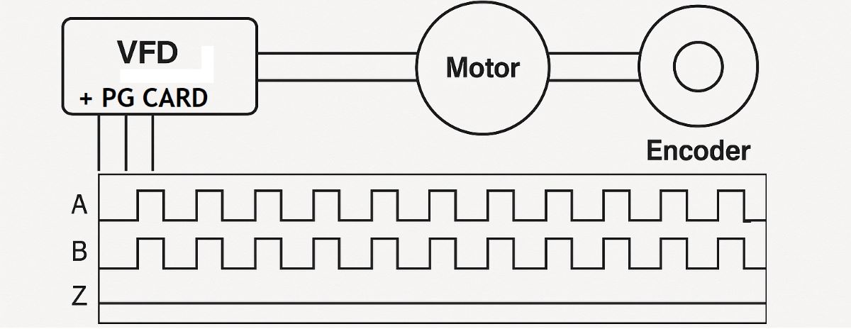
A PG card in a motor drive is an encoder feedback interface used to bring actual motor-speed, direction and, depending on the system, rotor-position information into a Variable Frequency Drive (VFD). In this context, PG generally refers to Pulse Generator.
PG does not mean “Programmable Gateway” in normal VFD feedback terminology. PROFINET, EtherCAT, CANopen, PROFIBUS and similar network option cards belong to the communication/fieldbus side of the drive. A PG or encoder-feedback card belongs to the motor-feedback loop.
Variable Frequency Drives › PG / Encoder Feedback Card › Encoder Signals › Vector Control › Sensorless Vector Control › Auto-Tuning
What does a PG card do?
In a closed-loop motor-control system, knowing the commanded VFD frequency is not enough. The drive needs to know how fast the shaft is actually rotating, which direction it is moving and how much its speed changes when mechanical load changes.
The motor encoder converts shaft rotation into electrical feedback. The PG card receives this encoder signal and delivers usable speed or position information to the drive control algorithm.
Speed Reference → Speed Controller → Motor → Encoder → PG Card → Measured Speed Feedback → Speed Controller
PG card vs communication card
| Option | Main function | Examples |
|---|---|---|
| PG / Encoder Feedback | Motor speed, direction or rotor feedback | A/B/Z, TTL, HTL, RS-422, SinCos, EnDat, HIPERFACE, SSI* |
| Fieldbus Card | Communication with PLC, SCADA or other network devices | PROFINET, EtherCAT, PROFIBUS, CANopen, EtherNet/IP |
| I/O Expansion | Additional analog and digital I/O | DI, DO, AI, AO, relay |
*Supported feedback interfaces depend entirely on the drive and option-card model.
What are A, B and Z encoder channels?
A conventional incremental encoder normally generates A and B quadrature channels separated by approximately 90 electrical degrees. Their phase sequence allows the drive to determine direction as well as pulse rate.
Many encoders also provide a Z or Index channel, typically one reference pulse per mechanical revolution. Not every encoder has a Z channel, and not every closed-loop VFD application requires it.
For a detailed explanation of A/B/Z, differential pairs, TTL, HTL and resolver signals, see Encoder Output Signal Types.
PG Card – A/B/Z Encoder Feedback Simulation
Motor speed:
1500 rpm
Encoder resolution:
Direction:
This demonstration treats PPR as pulse cycles per revolution on one channel. Manufacturers do not always use PPR and CPR terminology in the same way, so always verify the encoder data sheet.
A-channel frequency: 25.60 kHz
Theoretical x4 quadrature edge rate: 102.40 kcount/s
Z / Index frequency: 25.00 Hz
Feedback status: PG SIGNAL PRESENT
How is encoder pulse frequency calculated?
For a conventional incremental encoder, one channel's pulse-cycle frequency can be estimated as:
fencoder = PPR × RPM / 60
For example, a 2048 PPR encoder at 3000 rpm produces approximately 102.4 kHz on one channel.
If the controller decodes both rising and falling edges of both A and B channels, theoretical x4 quadrature processing corresponds to approximately 409,600 edges per second.
PPR and CPR terminology is not perfectly standardised between encoder manufacturers, so use the actual data-sheet definition when calculating PG-card input frequency.
Why does maximum PG input frequency matter?
Higher encoder resolution and higher shaft speed both increase feedback frequency. If that frequency exceeds the option card's capability, the result can be missing pulses, speed-feedback errors or feedback faults.
Some Yaskawa differential line-driver feedback cards, for example, support input frequencies around 300 kHz, while certain open-collector options have much lower limits. Electrical voltage compatibility alone therefore does not prove that an encoder/card combination is suitable.
TTL, HTL, differential and open-collector feedback
PG-card selection must include the electrical output type of the encoder.
TTL/RS-422 line-driver encoders commonly provide complementary pairs such as A+/A− and B+/B−. Differential signalling is highly useful for rejecting noise in industrial environments.
HTL uses higher signal levels, while open-collector feedback has different wiring and frequency limitations. For a deeper comparison, see Encoder Output Signal Types.
Differential is not itself an encoder measurement principle; it describes the way the signals are transmitted.
Does every PG card use A/B/Z?
No. A/B incremental feedback is extremely common, but modern drive-feedback modules can support TTL/RS-422, HTL, SinCos, resolvers and absolute feedback systems such as EnDat, HIPERFACE or SSI.
Yaskawa, ABB and Danfoss all offer families of feedback modules rather than one universal encoder card. The selected interface must match the actual encoder and motor-control mode.
Is a PROFINET or EtherCAT encoder a PG card?
Not in the normal VFD option-card sense. Encoders can certainly communicate through EtherCAT, PROFINET or CANopen, but that does not make a standard VFD fieldbus communication option equivalent to a PG feedback card.
A fieldbus option primarily connects the drive to a control network. A PG interface primarily supplies the motor-control algorithm with shaft feedback.
Which control modes use PG feedback?
The most familiar application is closed-loop vector control, where actual shaft speed is fed back to the speed regulator.
Depending on the drive, PG feedback may also be supported with V/Hz with feedback, permanent-magnet motor control or specialised motion functions.
Does Sensorless Vector Control need a PG card?
No. Sensorless Vector Control estimates motor state from measured electrical quantities and a motor model instead of reading a physical shaft encoder.
Encoder feedback becomes particularly useful where very low speed, tight speed regulation or rapid load response is important.
Does an encoder make auto-tuning unnecessary?
No. Encoder feedback measures motion. It does not provide all of the electrical motor parameters needed by the vector-control model.
Correct motor-nameplate data and auto-tuning can therefore remain important even when closed-loop encoder feedback is installed.
What if encoder direction is wrong?
The motor's commanded direction and measured feedback direction must agree. Incorrect A/B phase sequence or an incorrect feedback-direction parameter can create a direction fault or unstable speed-loop behaviour.
Feedback direction should therefore be verified during commissioning using the drive manufacturer's specified procedure.
What if the encoder supply voltage is wrong?
Some feedback cards can supply the encoder with 5 V, 12 V or 24 V, but this varies between models. Never assume the supply voltage from the connector alone.
Applying 24 V to a 5 V encoder can permanently damage it, while insufficient supply voltage can produce unreliable feedback.
Why is encoder wiring important around a VFD?
Encoder feedback is a sensitive measurement circuit operating close to a powerful PWM switching system. Motor cables can generate high dV/dt and common-mode interference.
Twisted-pair wiring, differential signals, correct cable shielding and manufacturer-specified shield termination are therefore important for reliable feedback, particularly with long cable runs.
What happens when encoder feedback is lost?
There is no universal behaviour. Depending on the VFD and its configuration, feedback loss can produce a warning, fault, trip or another predefined reaction.
For example, Danfoss feedback monitoring can be configured with responses such as None, Warning or Trip on supported systems. Do not assume that every VFD simply switches automatically to sensorless control.
PG card vs PLC high-speed counter
A PLC high-speed counter can also read encoder pulses, but it is not automatically a replacement for the VFD feedback interface. A PG card connects feedback directly into the motor-control loop.
Some PG cards also provide a buffered encoder output, allowing the same feedback signal to be passed onward to another controller.
What should be checked when selecting a PG card?
Check drive compatibility, encoder supply voltage, electrical output format, PPR/resolution, maximum shaft speed, calculated pulse frequency, A/B/Z or absolute-feedback format, maximum card input frequency and supported motor-control mode.
For example, a 2048 PPR encoder at 6000 rpm produces about 204.8 kHz on a single channel. That cannot be reliably read by an option limited to 32 kHz even if its voltage levels appear compatible.
Editor's note: On a PG-feedback fault I would not replace the option card first. Verify encoder power, A/B phase sequence, PPR configuration, maximum pulse frequency and feedback direction. If the machine runs correctly unloaded but develops feedback faults under load, inspect encoder cable routing and shielding as well. The PG card does not command the motor speed; its job is to tell the drive what the shaft is actually doing. Bad feedback makes even an excellent controller make bad decisions.
Related topics
Encoder Output Signal Types — A/B/Z, TTL, HTL, differential and other feedback interfaces
What is Vector Control? — closed-loop and sensorless motor control
What is Sensorless Vector Control? — vector control without shaft feedback
What is Auto-Tuning? — identification of motor electrical parameters
What is a VFD? — main variable-frequency-drive guide
In summary: A VFD PG card is a Pulse Generator / encoder-feedback interface, not a generic programmable gateway or fieldbus card. It provides the drive with actual motor-speed and direction information. Correct operation requires compatibility not only with the drive but also with the encoder signal type, voltage, resolution, maximum pulse frequency, direction and wiring method.