
What is FOC Vector?
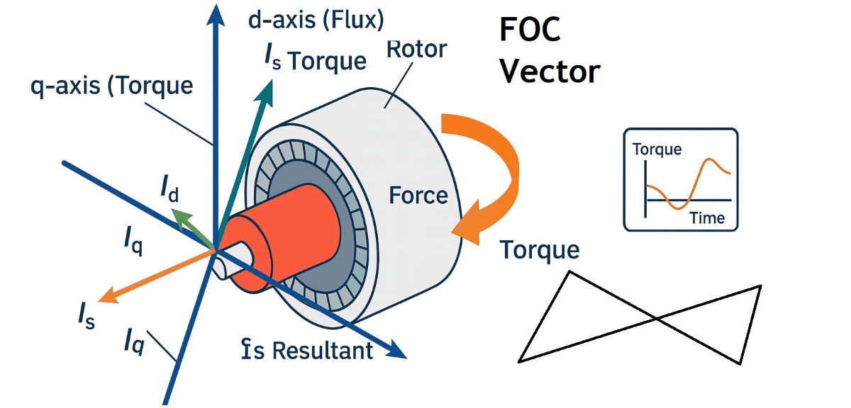
What is FOC – Field-Oriented Control?
FOC – Field-Oriented Control is an advanced AC motor-control method that transforms the motor's three-phase currents into a rotating reference frame so that flux-producing current and torque-producing current can be controlled separately.
Instead of treating Ia, Ib and Ic simply as three sinusoidal currents, FOC converts them into two useful control quantities: Id and Iq. In the conventional teaching model, Id mainly controls flux while Iq mainly controls torque.
This is a major difference from basic V/F control, which mainly manages the voltage-to-frequency relationship. FOC uses a motor model, measured current and electrical-angle information to control the motor much more dynamically.
Explore the OtomasyonAVM knowledge base: Vector Control · FOC Vector · V/F Control · Torque Control · Auto-Tuning · Encoders · PG Cards
How does FOC work?
The drive first measures the motor phase currents Ia, Ib and Ic. A Clarke transformation converts those three quantities into a stationary two-axis α–β representation. A Park transformation then rotates that coordinate system into the d–q frame using the motor's electrical angle.
The controller now works with Id and Iq rather than three continuously changing phase currents. Fast PI current controllers compare the requested d- and q-axis currents with the measured values and calculate the voltage vector required to correct the error.
The calculated voltage command is then converted back into a form that the inverter can produce, and PWM or space-vector modulation controls the semiconductor power stage.
In short: measure current → determine electrical angle → transform to Id/Iq → regulate current → calculate the voltage vector → apply it through PWM.
Compact FOC control-chain demo
With flux held approximately constant, increasing Iq increases torque demand.
Does Id always mean flux and Iq always mean torque?
That is an excellent teaching model, but the exact relationship depends on the motor type and chosen reference frame. In an induction-motor FOC system where the d-axis is aligned with rotor flux, Id mainly establishes flux while Iq mainly produces torque.
If flux remains approximately constant, motor torque can be treated as roughly proportional to Iq. In the real machine, however, torque also depends on flux; it is not literally determined by Iq alone.
Permanent-magnet motors add further detail. Their d-axis current may be near zero in one operating region and deliberately negative during field weakening or depending on the motor design.
Is the current vector parallel to the flux vector?
Not in the general FOC sense. The entire point of the rotating d–q frame is to separate the current into a component aligned with the flux axis and a quadrature component approximately 90 electrical degrees away that produces torque.
If the complete current vector were simply aligned with the flux vector, there would be no separate q-axis torque component.
For the wider picture, see our Vector Control guide.
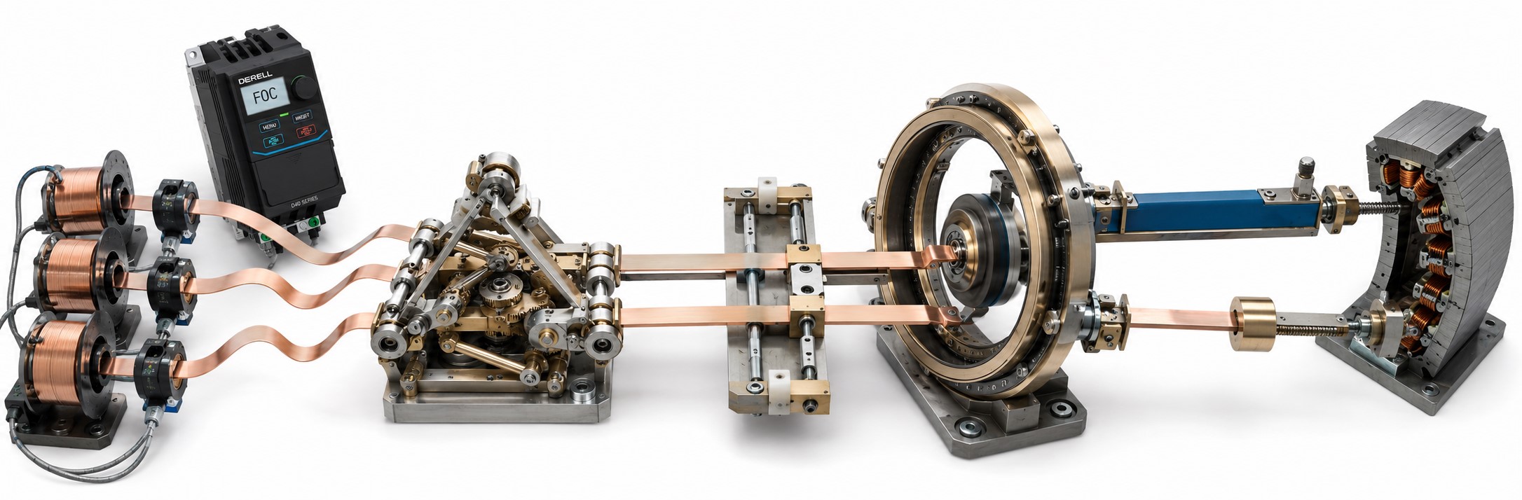
Why does FOC need electrical-angle information?
After Clarke transformation, the α–β quantities are still referenced to a stationary coordinate system. To transform them into the rotating d–q frame, the controller needs to know the electrical angle of the selected flux or rotor reference.
That angle can come from an encoder or resolver, or it can be estimated by a sensorless motor model. When encoder feedback is used on a VFD, a PG card may provide the feedback interface.
This is one of the reasons FOC naturally connects to both closed-loop vector control and sensorless vector control.
Why is Auto-Tuning important?
FOC depends on an internal mathematical motor model. Incorrect motor information can therefore produce incorrect flux, slip or angle estimates.
A proper Auto-Tuning procedure helps the drive identify important characteristics of the connected motor and gives the controller a more accurate model to work with.
Editor's note: FOC is only as good as the information it is working with. Selecting a sophisticated control mode while entering the wrong motor data simply gives you a sophisticated calculation based on bad information. My order would be motor nameplate → wiring → control mode → auto-tune → actual current before touching PI gains.
Is FOC the same as closed-loop vector control?
Not exactly. FOC describes a control method. That method can use direct shaft feedback or a sensorless observer.
With an encoder, the controller has real shaft-speed or position information and can achieve much tighter regulation, particularly at very low speed and during fast load changes.
Without an encoder, a modern drive may still use a sophisticated sensorless motor model. The achievable low-speed performance then depends on the drive, motor and operating conditions.
Is FOC the same as servo control?
No, although FOC is widely used inside modern servo systems.
A servo normally includes a motor, drive, high-resolution feedback and nested position, speed and current loops designed as a motion-control system. A standard induction motor running from a FOC-capable VFD can achieve excellent speed and torque control without becoming a servo positioning system.
How are the FOC control loops arranged?
The fastest loops are normally the inner Id and Iq current loops. A slower speed loop may sit around those current loops. In a position-controlled servo system, a still slower position loop can sit outside the speed loop.
This hierarchy matters because torque-producing current must respond much faster than the overall machine-speed loop.
What does current limiting do in FOC?
Demanding more torque usually means demanding more Iq, but the motor and semiconductor power stage cannot carry unlimited current. Real drives therefore apply current and torque limits.
If the machine jams, FOC cannot simply keep increasing Iq forever. Once the drive reaches its current capability, the controller has to limit torque or protective functions will intervene.
How is FOC related to the DC bus and PWM?
The FOC algorithm calculates what voltage and current vector the motor needs, but the physical energy comes from the drive's DC bus.
The inverter uses PWM or space-vector modulation to switch that DC-link voltage into the motor phases. In simple terms, FOC decides the required vector; the inverter and PWM create it electrically.
Does FOC automatically improve efficiency?
Not automatically. Its primary advantage is improved dynamic speed and torque control. Overall energy consumption still depends on the mechanical load, motor efficiency, operating point and drive losses.
Some drives include additional flux-optimization or energy-saving algorithms that can reduce magnetizing losses under light load, but that is not the same as saying that selecting FOC always guarantees an energy saving.
The same caution applies to vibration and noise. Correct control can improve behaviour, but poor motor data, bad tuning or mechanical resonance will not disappear simply because FOC is selected.
Where is FOC used?
FOC is widely used where machines need fast torque response, stable low-speed operation or tight speed regulation: cranes, extruders, winding systems, heavy conveyors, spindles, electric traction and servo motion systems.
At machine level, the drive can exchange commands and diagnostic values with a PLC or HMI, allowing actual current, speed, torque estimate and fault information to become part of the wider automation system.
In short: FOC transforms three-phase motor currents into a rotating d–q reference frame, controls flux and torque components separately, then applies the calculated voltage command through the inverter. Continue through the OtomasyonAVM knowledge base with Vector Control, V/F Control, Torque Control, Auto-Tuning, Encoders, PG Cards, Servo Systems and the main VFD Technical Guide.