
How is PLC programming done in CoDeSys?
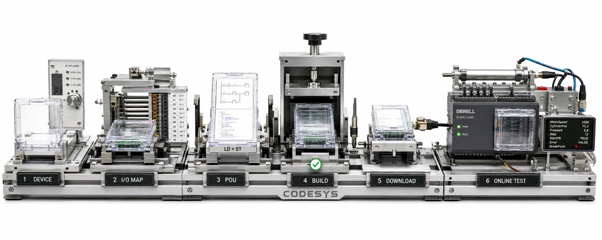
How do you program a PLC with CODESYS?
PLC programming with CODESYS starts with defining the process and brings together device configuration, code, tasks, I/O mapping and testing. The runtime executes the application developed in the CODESYS platform on the target device. Correct code needs the correct device configuration and connections to produce the intended behaviour.
This guide follows the CODESYS Development System V3 layout. Menu names may vary with the manufacturer package and software version. We will build the initial example in simulation, then examine the settings needed when moving to a real PLC.
1. Write down what the machine should do
For the PLC project you intend to develop, define the inputs, expected results and interruption scenarios. “Raise a warning when the level is high” leaves questions unanswered: should the warning disappear when the level returns to normal? What happens if reset is active while the level is still high? These decisions become the rules of an industrial automation application.
In our example, a high-level warning sets a software alarm variable to TRUE. The warning remains after the level returns to normal and clears when reset is TRUE and the high-level condition is absent. This demonstrates both responding to an input and retaining the previous state. The example variables are not mapped to physical outputs.
2. Select a compatible PLC and software package
When selecting hardware for CODESYS, check the supported runtime, device description, communication interfaces and manufacturer packages. Not every PLC can be programmed with CODESYS. When downloading the software, use the version and required add-ons recommended by the device manufacturer.
One of the features that distinguish CODESYS from other PLC software is a common engineering approach across compatible targets from different manufacturers. Moving a project still requires reassessing I/O channels, libraries and timing. Selecting a PLC from a list does not, by itself, verify that its configuration matches the actual device.
3. Create the project and choose a language
Use File → New Project to open an appropriate template. When creating the project, select the target device and establish the application structure. Add the required modules and communication devices to the device tree; manage library dependencies through Library Manager.
The programming languages associated with IEC 61131-3 offer different ways to express logic. LD suits contact logic, FBD connects blocks, and ST expresses conditions and calculations as text. SFC organises sequences through steps and transitions. IL may appear in older projects; CODESYS states that its editor is no longer maintained. We will use Structured Text for the introductory example.
4. Understand Program, Function and Function Block
A POU is a program organisation unit, created under Application using Add Object → POU. A Program can organise the application's control flow and be called from a task. If a suitable PLC_PRG already exists, you can use it as your starting point.
A Function performs work such as a calculation or conversion without retaining internal state between calls. A Function Block can retain state in each of its instances. Two timers tracking separate delays depend on that distinction between instances. Functions and function blocks help create organised, reusable structures for similar machine sections.
Select data types that match the meaning of the information: BOOL represents a logical state, INT an integer, REAL a decimal measurement and TIME a duration. Meaningful names and comments help maintenance engineers identify where each value comes from.
5. A small example: A level warning that remains until reset
Place the following VAR block in the program's declaration area, keeping the PROGRAM line created by the editor. The second section belongs in the implementation area. Among the statements and operators, := assigns a value, while IF and ELSIF determine the order in which conditions are evaluated.
Variable declarations:
VAR
    xHighLevel : BOOL := FALSE;
    xReset     : BOOL := FALSE;
    xAlarm     : BOOL := FALSE;
END_VAR
Code executed on each program call:
IF xHighLevel THEN
    xAlarm := TRUE;
ELSIF xReset THEN
    xAlarm := FALSE;
END_IF;
The high-level condition takes priority. If xHighLevel is TRUE, the alarm remains TRUE even when reset is also TRUE. When both inputs are FALSE, neither branch assigns xAlarm, so it retains its previous value. Retaining state between cycles does not guarantee that the same state will survive a power interruption. Restart behaviour requires its own design.
| Trial | Expected result |
|---|---|
| High-level input is TRUE | The alarm becomes TRUE. |
| Level returns to FALSE; reset remains FALSE | A previously triggered alarm remains TRUE. |
| Level is FALSE; reset is TRUE | The alarm becomes FALSE. |
| Level and reset are both TRUE | High level takes priority; the alarm remains TRUE. |
6. Configure the task call and I/O mapping
Under Task Configuration, add your program to a task's Program Calls list. Do not duplicate an existing call. Task scheduling determines the execution interval and priority. Creating a POU does not automatically execute it. Monitor task execution time and timing variation on the actual target.
For real hardware, use the I/O Mapping section of the input and output modules to link physical channels to project variables. Verify the sensor's electrical signal, channel type and active state. Remote I/O also requires its associated fieldbus configuration. Networking and data transfer settings form separate layers that work together with the application code.
7. Generate the code and test in simulation
Generate the application code using Build → Generate Code, or F11, and resolve errors in the message view. Then use Online → Simulation, Online → Login and Debug → Start. The Start shortcut is F5. On first login, you may be prompted to create the simulated application.
During debugging, prepare values for xHighLevel and xReset, then apply them with Debug → Write Values. Run the trials in the table and observe xAlarm. Simulation does not update physical I/O channels or send fieldbus telegrams. An application compiling without errors does not prove correct behaviour under every operating condition.
8. Connect to the real PLC, download and observe
To leave simulation, log out and disable Simulation. In the device's Communication Settings, select the correct gateway and connection path. Verify that the device found during a network scan is the intended PLC; provide the user permissions and certificates required by that target.
Online → Login may offer download or online-change options depending on the existing application. Download and online change are different operations; assess the differences shown and their effect on the application. Use Debug → Start to run it. CODESYS security also involves connection permissions, project backups and records of the deployed version.
9. Complete the boot application and handover files
The boot application is the application version used when the controller is powered on or started. Check that it is updated on the target; use Online → Create Boot Application when necessary. Separately test initial values, alarm states and output behaviour after power returns. The current engineering project and the target's boot application should represent the same version.
If the PLC works with SCADA, test status reporting, command permissions and behaviour during communication loss as well. Retain the project archive, device and library versions, I/O list and test results together at handover. Future maintenance then has a record of both the code and the configuration in which it was verified.
Official technical references: CODESYS Development System, I/O configuration, Login and download options and boot application.