
What is the structure of an Ethernet frame?
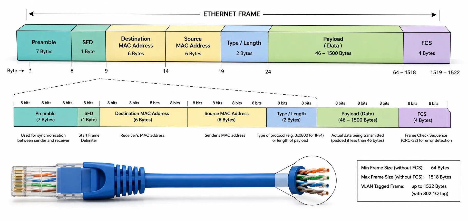
An Ethernet frame is the Layer-2 data structure used to carry higher-layer information across an Ethernet link. One detail matters immediately: not every byte transmitted on the wire is part of the MAC frame itself. In IEEE 802.3 terminology, the MAC frame runs from the Destination Address through the end of the FCS. The 7-byte preamble and 1-byte Start Frame Delimiter are part of the physical packet start, not part of the MAC frame length. [1]
That distinction prevents many mistakes when discussing frame size, MTU, VLAN tags and packet captures. A basic untagged Ethernet MAC frame is normally 64 to 1518 bytes, including the FCS but excluding the preamble and SFD. IEEE working documents state the basic frame range as 64–1518 octets. [2]
Basic Ethernet transmission view — the MAC frame is deliberately separated from the additional on-the-wire fields.
| Preamble 7 B outside MAC frame |
SFD 1 B outside MAC frame |
Destination MAC 6 B |
Source MAC 6 B |
Length / EtherType 2 B |
Data + pad if needed 46–1500 B basic untagged form |
FCS 4 B |
IFG 96 bit-times outside frame |
| Physical packet start | MAC frame: Destination Address through FCS | Gap between frames | |||||
What fields are in an Ethernet MAC frame?
| Field | Size | Purpose | Important detail |
|---|---|---|---|
| Destination MAC Address | 6 bytes | Identifies the Layer-2 destination of the frame. | May be unicast, multicast or broadcast. |
| Source MAC Address | 6 bytes | Carries the source address of the transmitting Ethernet interface. | Switches can learn source MAC locations from received frames. |
| Length / EtherType | 2 bytes | Depending on its value, indicates a data length or identifies the higher-layer protocol. | ≤1500 means Length; ≥1536 (0x0600) means EtherType. Values 1501–1535 are not assigned to either interpretation. [3] |
| MAC Client Data + Pad | 46–1500 bytes in the basic form | Carries an IP packet, ARP, industrial-protocol data or another upper-layer payload. | Padding may be added to satisfy the minimum frame size. |
| FCS | 4 bytes | Provides CRC-32 based error detection. | It does not repair the data or provide retransmission by itself. |
For the addressing fields, see Ethernet / MAC addresses; for forwarding through switches, see Ethernet data transmission and switch vs. hub.
Why are the preamble and SFD not counted in the MAC frame?
The preamble is a 7-byte synchronization pattern followed by a 1-byte Start Frame Delimiter (SFD). These fields help the receiving physical layer lock onto the transmission and identify where the MAC frame begins. IEEE 802.3 editorial terminology explicitly distinguishes a “frame/MAC frame,” running from Destination Address to FCS, from a “packet/MAC packet,” which includes the preamble, SFD and, where applicable, extension. [1]
Therefore, when we say “the minimum Ethernet frame is 64 bytes,” those 64 bytes do not include the eight bytes of preamble plus SFD. If you are calculating total on-the-wire time, those additional fields must still be considered.
How is the 64-byte minimum frame formed?
For a basic untagged frame, the arithmetic is straightforward: 6-byte destination MAC + 6-byte source MAC + 2-byte Length/EtherType + at least 46 bytes of data/pad + 4-byte FCS = 64 bytes. IEEE material defines the minimum frame from Destination Address through FCS as 64 octets. [2]
If the upper layer provides less data than required, the frame is not simply transmitted below the minimum size. The MAC can add padding. RFC 894 describes this for IPv4 over Ethernet: the Ethernet data field must be padded when necessary to meet the minimum, and the padding is not part of the IP packet itself. [4]
1518-byte frame size and 1500-byte MTU are not the same thing
For the basic untagged form, the familiar 1518-byte maximum is the Layer-2 MAC frame size: 14 bytes of destination/source/type-length information, up to 1500 bytes of MAC client data, and 4 bytes of FCS. The familiar 1500-byte MTU, by contrast, describes the maximum higher-layer packet size typically carried as Ethernet payload in common IP use. RFC 894 specifies the 1500-byte IPv4 limit for Ethernet, while RFC 2464 defines a default Ethernet MTU of 1500 bytes for IPv6. [4] [5]
So MTU is not the size of the complete Ethernet frame. This distinction becomes important when troubleshooting VPNs, tunnels, VLANs and jumbo-frame configurations.
How is the Length / EtherType field interpreted?
The same two-byte field can serve two purposes. A value of 1500 or less is interpreted as the number of MAC client data octets that follow. A value of 1536 or greater (0x0600 and above) is interpreted as an EtherType identifying the protocol carried in the payload. Values from 1501 through 1535 sit between those two interpretations. IEEE text explicitly separates the Length and Type interpretations. [3]
Common examples include 0x0800 for IPv4, 0x0806 for ARP and 0x8100 for an 802.1Q Customer VLAN Tag. IANA's IEEE 802 number registry lists these and many other assignments. [6] Industrial Ethernet technologies may also use their own EtherTypes; see EtherCAT for one example.
How does an 802.1Q VLAN tag change the frame?
With 802.1Q VLAN tagging, a 4-byte VLAN tag is inserted after the Source MAC Address. As a result, the basic untagged maximum of 1518 bytes becomes a commonly encountered 1522-byte maximum for a single-tagged MAC frame. IEEE frame-expansion material shows a 64–1518 byte basic MAC frame and a maximum of 1522 bytes for a tagged frame. [7]
| Format | Basic field order | Standard size view |
|---|---|---|
| Untagged | DA | SA | Length/EtherType | Data/Pad | FCS | 64–1518 byte basic MAC frame |
| 802.1Q tagged | DA | SA | 802.1Q Tag | Length/EtherType | Data/Pad | FCS | The tag adds 4 bytes; maximum 1522 bytes. A valid tagged MAC frame can still have a 64-byte minimum because padding can be adjusted. [7] |
A VLAN tag is not merely “four extra bytes.” It also carries Layer-2 information such as priority, drop eligibility and VLAN identity. VLAN behaviour belongs mainly to the IEEE 802.1 bridging family and should not be treated as the same thing as the Ethernet PHY.
What exactly does the FCS check?
The Frame Check Sequence (FCS) is four bytes and is used for CRC-32 error detection. In the basic frame, the protected content runs from the Destination Address through the fields before the FCS; the receiver compares its own CRC calculation with the received FCS. IEEE working material describes the frame from DA through FCS as being checked by CRC32. [2]
Two misconceptions are worth removing. First, FCS does not correct damaged data. Second, Ethernet MAC does not provide a TCP-like acknowledgement/retransmission mechanism for a corrupt frame. If retransmission is required, TCP or the application/industrial protocol can provide its own recovery method. See the Ethernet protocol and how Ethernet works for the layer separation.
Why doesn't Wireshark always show the preamble or FCS?
A packet-capture application does not necessarily receive every bit that was present on the wire. Ethernet hardware normally handles the preamble/SFD before giving the frame to the operating system. Similarly, many NICs and drivers remove the FCS before delivering captured packets. The Wireshark Ethernet documentation explains that applications usually do not receive the preamble and may or may not receive the FCS depending on hardware and driver behaviour. [8]
So seeing a “1514-byte frame” in Wireshark does not prove that Ethernet transmitted no FCS. You need to know what the capture interface actually provides. Wireshark's own FAQ notes that most operating systems do not make Ethernet FCS available to capture programs. [9]
Is the Interframe Gap part of the frame?
No. The Interframe Gap (IFG) is the idle interval between consecutive Ethernet frames. IEEE MAC parameters commonly express the nominal gap as 96 bit-times. [2] It is not a Length/EtherType, payload or FCS field, but it does consume line time and therefore matters when calculating practical link efficiency.
For very small frames, ignoring the preamble/SFD and IFG can significantly understate the real on-the-wire overhead. That is one reason why a link's raw bit rate and its useful application throughput are different quantities; see Ethernet speeds.
What is a jumbo frame? Is 9000 bytes an official universal value?
Jumbo frame is a general term for Ethernet frames carrying more than the conventional 1500-byte MTU. It is not correct to say that “jumbo always means exactly 9000 bytes and that 9000 is the one IEEE Ethernet standard value.” RFC 3635 states that the defined standard MTU for Ethernet-like interfaces is 1500 octets while noting that many implementations support larger packet sizes than the IEEE 802.3 standard. [10]
If jumbo frames are used, both endpoints and every intermediate switch or Layer-3 device in the path must support the selected size. An MTU mismatch can produce drops, fragmentation or the classic symptom where small traffic works but larger transfers fail. In an industrial network, enable larger MTUs only when the application and all relevant equipment are documented and tested for them.
Where is the PLC message inside the frame?
If a PLC and an HMI communicate with an IP-based protocol such as Modbus TCP, the PLC application data is not itself an “Ethernet header.” The application data can be encapsulated in TCP/UDP and IP, and the resulting IP packet is then carried in the Ethernet frame's payload. RFC 894 describes IPv4 datagrams being carried in the Ethernet data field with EtherType 0x0800. [4]
Some industrial Ethernet protocols do not use TCP/IP for every cyclic real-time transfer. EtherCAT and some PROFINET real-time traffic can use Ethernet frames more directly. That is why “Ethernet payload always equals an IP packet” is also too broad. See protocols that can operate over Ethernet for the larger protocol map.
Why does frame size matter when troubleshooting a plant network?
Switches and NICs may expose counters such as CRC/FCS errors, undersize/runts, oversize/giants and drops. The exact counter definition depends on the vendor, but frame length and FCS information can be extremely useful when diagnosing the physical path. Damaged cable, poor connectors, EMI, duplex problems or failing PHY hardware can leave clues in those counters.
A useful troubleshooting path is to start with the NIC / Ethernet interface and peer-port link state, then inspect cable and error counters, and only then move up into VLAN/IP and the application protocol. For the physical side, see Ethernet cable types and maximum Ethernet cable length.
Five common frame-size mistakes
1. “The preamble is the first seven bytes of the frame.” It precedes the MAC frame on the physical transmission but is not counted in the IEEE MAC frame length.
2. “The 64-byte minimum excludes the FCS.” It does not; the basic 64-byte MAC frame includes FCS.
3. “1518 bytes is the Ethernet MTU.” No; 1518 is the basic untagged MAC-frame size, while the conventional Ethernet/IP MTU is 1500 bytes.
4. “FCS repairs a bad bit.” It does not; it detects corruption.
5. “If Wireshark does not show FCS, the frame had no FCS.” Not necessarily; the NIC or driver may have removed it before capture.
In one paragraph
A basic Ethernet MAC frame contains Destination MAC + Source MAC + Length/EtherType + Data/Pad + FCS. The preamble and SFD precede the MAC frame on the physical link, while the IFG is the idle interval between frames. A basic untagged MAC frame is 64–1518 bytes. A single 802.1Q VLAN tag adds four bytes and can raise the maximum to 1522 bytes. The conventional Ethernet MTU is 1500 bytes; it is not the size of the entire frame. FCS detects transmission errors but does not correct the data.
Related Ethernet guides
What is Ethernet? • How does Ethernet work? • Ethernet protocol • MAC address • Ethernet card / NIC • Switch vs. hub • Ethernet data transmission • Ethernet speeds • Gigabit Ethernet • Ethernet cable types • Maximum cable length • PoE • Ethernet security • Industrial communication