
what is ASR (Auto Speed Regulation) in vfd?
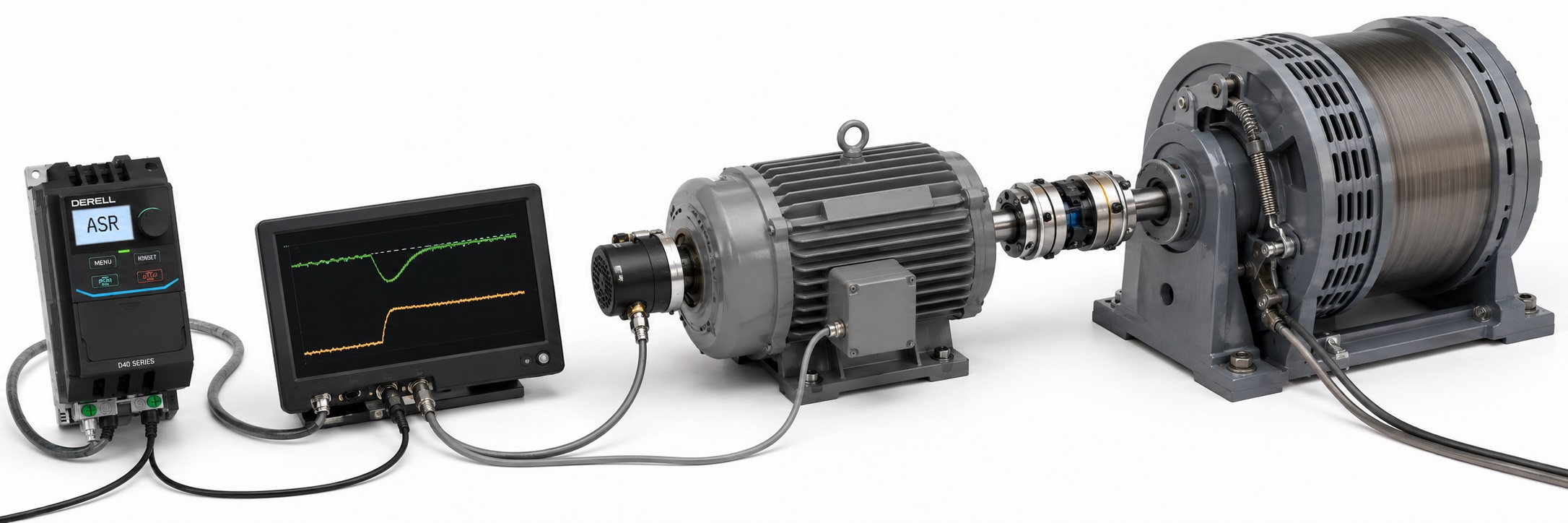
ASR – Automatic Speed Regulator is the speed-control loop used in many Variable Frequency Drive (VFD) control systems. It compares the commanded speed with the motor's actual or estimated speed and adjusts the motor-control command to reduce the resulting speed error.
The word “automatic” can be misleading. ASR does not primarily decide what speed the process should run at. Its job is to make the motor follow the speed reference it has already been given.
If a motor is commanded to run at 1200 rpm and a sudden load increase pulls the actual speed down, the ASR detects the error and demands additional torque. If the motor and drive still have sufficient current and torque capability, the speed is brought back toward 1200 rpm.
A useful one-line definition is therefore: ASR keeps actual motor speed close to commanded motor speed despite disturbances such as load changes.
How does ASR work?
The control system first receives a speed reference. This reference can come from the keypad, an analog input, PLC, fieldbus, preset speed, process PID controller or another supervisory controller.
The drive then needs information about motor speed. Depending on the control method, this can come from a physical encoder / pulse generator or from an internally estimated speed produced by a sensorless motor model.
The regulator calculates:
Speed error = Speed reference − Actual speed
If the motor is too slow, the regulator increases the control effort. If it is too fast, the control effort moves in the opposite direction.
Many industrial drives implement this speed regulator as a PI – Proportional plus Integral controller. Parameters may therefore appear as ASR P Gain, ASR Integral Time, Speed Loop Gain or similar manufacturer-specific names.
Does ASR simply change output frequency?
Not in every control mode.
In a simple V/Hz system with speed feedback, the ASR may correct the frequency command in order to reduce speed error.
In a modern vector-control system, however, the speed regulator is often part of a cascaded controller. The ASR determines how much motor torque is required, and a faster inner torque/current loop produces that torque.
A simplified control chain is:
Speed Reference → ASR Speed Loop → Torque Reference → Current/Torque Loop → Motor → Speed Feedback → ASR
This is a more accurate model than describing ASR simply as a function that “changes frequency when the load changes.”
Existing ASR simulation
The existing OtomasyonAVM simulation is retained because the concept is useful. With ASR enabled, a load step causes a temporary speed error and the PI regulator increases drive command to restore speed. With ASR disabled, the same open-loop command produces more noticeable speed droop as load increases.
Automatic Speed Regulator (ASR) – Live Simulation
Speed Setpoint (rpm): 1200
Initial Load (%): 20
Try it: Allow the system to settle near 1200 rpm and then apply a +40% load step. With ASR enabled, watch the regulator restore motor speed. Disable ASR and repeat the same test to see open-loop speed droop.
Note: This is a simplified educational model designed to demonstrate speed-regulator behaviour. Real motor torque, current, inertia and loop dynamics depend on the actual VFD, motor and mechanical load.
ASR and process PID are not the same thing
This is one of the most important distinctions on this page.
ASR regulates motor speed. If the speed reference is 1200 rpm, its job is to keep actual motor speed close to 1200 rpm.
Process PID control regulates a process variable such as pressure, flow, temperature or level.
In a booster-pump system, for example, a pressure transmitter can send a 4–20 mA feedback signal to the VFD's process PID controller. The PID may decide that the required motor-speed reference should increase from 38 Hz to 44 Hz in order to restore pressure.
If an ASR speed loop is also used, its job is then to make the motor accurately follow that newly commanded speed.
The two loops can therefore operate in cascade:
Pressure Sensor → Process PID → Speed Reference → ASR → Torque/Current Control → Motor
For that reason, saying “ASR changes fan or pump speed according to process demand” mixes two different control functions.
ASR vs open-loop motor control
With basic open-loop V/Hz control, the drive applies a commanded frequency without necessarily feeding actual shaft speed back into a speed regulator.
As induction-motor load increases, slip increases and actual rotor speed can fall.
With a feedback-based speed loop, that reduction is measured or estimated. The ASR requests additional torque in an attempt to bring actual speed back toward the reference.
This is why ASR is closely related to the wider subject of closed-loop speed regulation.
Can sensorless vector control use a speed regulator?
The absence of a physical encoder does not necessarily mean that there is no internal speed-regulation loop.
Sensorless Vector Control can estimate motor speed and rotor state from electrical measurements and a motor model. A drive can use that estimated speed inside its control structure.
At very low or near-zero speed, however, sensorless estimation can become more difficult. High-performance applications may therefore use encoder-based closed-loop vector control.
What does ASR P Gain do?
Proportional gain determines how strongly the speed loop responds to the current speed error.
If P gain is too low, the motor can recover slowly after a load disturbance.
If it is too high, the speed loop can become overly aggressive and may oscillate depending on load inertia, mechanical compliance and feedback quality.
The objective is therefore not maximum gain. It is the highest practical responsiveness that remains stable on the real machine.
What does ASR Integral Time do?
The integral action accumulates speed error over time and attempts to remove steady-state error.
For example, proportional action alone may leave a motor running continuously at 1185 rpm when the reference is 1200 rpm under load. Integral action keeps correcting the output until that persistent error is reduced.
Excessive integral action can cause overshoot, hunting or oscillation.
Manufacturers may express this adjustment as integral gain or integral time. With an integral-time parameter, a smaller value commonly produces more aggressive integral action, but the exact parameter definition should always be checked in the manual.
Why does load inertia affect ASR tuning?
A small unloaded motor and the same motor coupled to a large flywheel do not respond to the same speed-loop tuning in the same way.
Mechanical inertia determines how quickly speed can physically change. High-inertia systems can require a slower and more carefully tuned loop.
This is why some advanced drives provide ASR tuning or inertia tuning. Current Yaskawa parameter structures, for example, include a dedicated ASR and Inertia Tuning group.
What happens when ASR reaches another drive limit?
The speed regulator can request more torque, but the drive cannot produce unlimited current.
Suppose a conveyor jams and motor speed drops. The ASR requests increasing torque. If motor current reaches the drive's current limit, the requested torque may no longer be available.
The motor can then remain below commanded speed even though the ASR is fully trying to correct the error.
In other words, ASR tries to maintain speed; current, torque, thermal and mechanical limits determine how much correction is actually possible.
What if encoder direction is wrong?
Encoder direction and scaling are critical in closed-loop systems.
If the motor runs forward but feedback reports reverse speed, the speed regulator interprets the error incorrectly and may demand excessive torque.
During commissioning, encoder direction, PPR/resolution, pulse scaling and actual shaft direction should therefore be verified at a safe low speed.
Feedback-loss behaviour is also manufacturer-specific. Depending on configuration, a drive may trip, perform a controlled stop or use another permitted control mode.
Does ASR save energy?
Energy saving is not the primary purpose of ASR. Its primary function is speed regulation.
Major energy savings in centrifugal fans and pumps come from operating the process at the speed actually required. A process PID, PLC or other supervisory controller normally determines that speed demand.
ASR can then help the motor accurately track the resulting speed reference despite changing load.
Energy optimization and speed regulation can therefore exist in the same drive, but they are not the same function.
ASR, Auto-Tuning and AFR are different functions
Auto-Tuning identifies or refines motor parameters used by the motor-control model during commissioning.
ASR is the running speed-regulation loop.
AFR – Auto Frequency Regulator is a different manufacturer-specific regulation or stability function on drives that use that terminology.
The names look similar, but the functions should not be mixed.
Where is ASR particularly useful?
Conveyors: Maintaining line speed as load varies.
Winders and unwinders: Synchronizing shaft or line speed with other sections of a machine.
Extruders: Holding screw speed stable despite changing process torque.
Test stands: Maintaining rotational speed inside a defined tolerance while load changes.
Lifting and elevator applications: Where the selected control architecture requires accurate low-speed regulation.
Multi-axis machinery: Maintaining speed relationships between mechanically or electronically coordinated axes.
On fans and pumps, the more important outer loop may instead be pressure or flow control, which is why the distinction between ASR and process PID matters.
Editor's Note – how I think about ASR in the field
I reduce ASR to one practical question: I told the machine to run at 1200 rpm; when load arrives, does it actually stay around 1200?
If the reference still says 1200 but the shaft settles at 1100 rpm, looking only at the reference tells you nothing about what the machine is really doing. That is where feedback and the speed regulator become useful.
But maximum ASR gain is not good tuning. If the loop is too aggressive, a conveyor can hunt every time the load changes. One person blames the encoder, another blames the gearbox, while the real problem may simply be poor speed-loop tuning.
Before tuning ASR I check the motor data and Auto-Tuning. If an encoder is installed, I verify its direction and scaling at low speed. Only then do I start changing proportional gain and integral time.
Another common confusion is process PID. If pump pressure drops and the motor command changes from 40 Hz to 45 Hz, that speed change was probably requested by the process loop. If the motor cannot accurately hold the commanded speed under load, then we are talking about the motor speed loop.
The useful rule is simple: know which loop you are tuning. Are you controlling motor speed, pressure, torque, position or temperature? If that question is unclear, parameter tuning quickly becomes guesswork.
What should you read next?
For the physical feedback side of ASR, continue with Encoders and the closed-loop motor-control topics.
For high-performance operation without a physical speed encoder, read Sensorless Vector Control. For establishing the motor model before tuning the speed loop, continue with Auto-Tuning.
For pressure, flow and temperature control rather than motor-speed regulation, use PID with VFD.
Related OtomasyonAVM sections
For real AC drive models, continue to AC Drives / VFDs. For feedback hardware use Encoders. For machine-level supervisory control, see the PLC section, and for higher-performance closed-loop motion continue to Servo Systems.
External technical reference
For manufacturer-level ASR terminology and tuning, Yaskawa's A1000 Technical Manual documents C5 – Automatic Speed Regulator (ASR), including proportional gain and integral-time adjustment. Newer Yaskawa parameter structures also list ASR, PID Control and Energy Saving as separate functional groups, which is a useful reminder that motor speed regulation and process-energy optimization are different control tasks.