
What is servo with EtherCat?
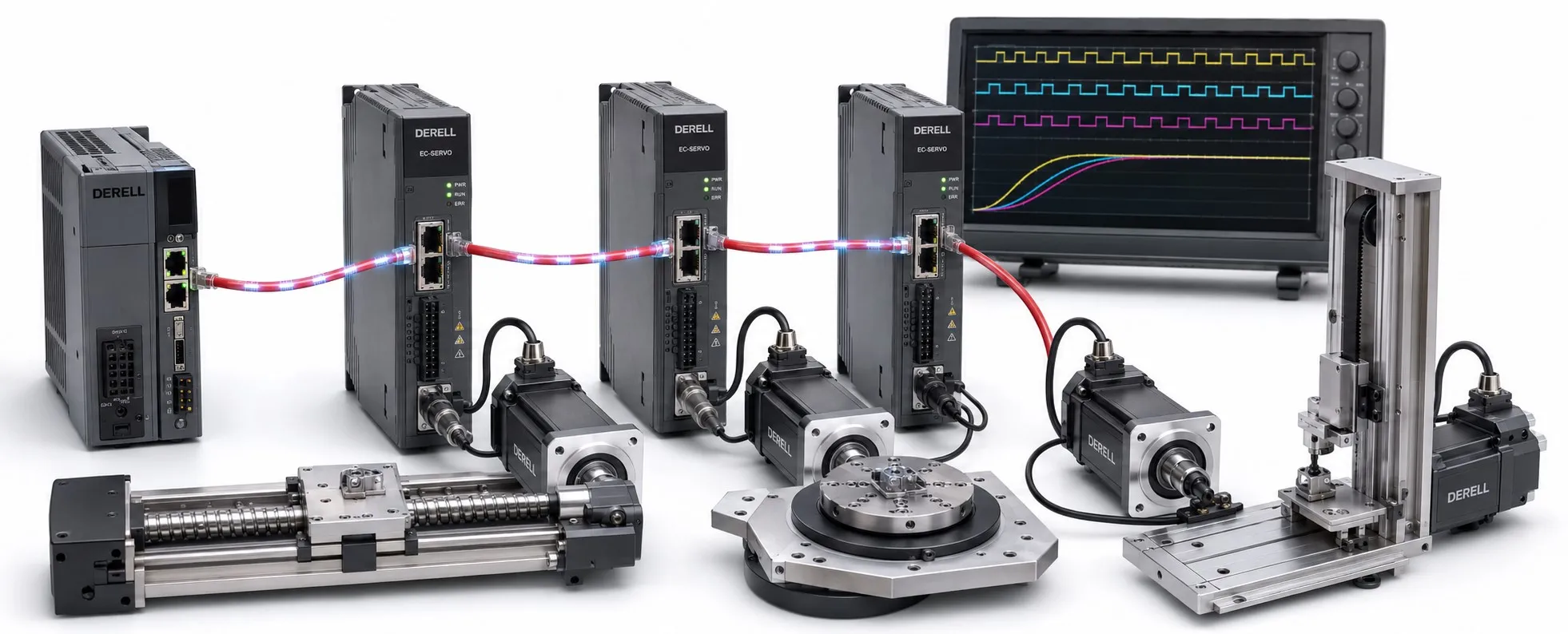
What is an EtherCAT servo?
An EtherCAT servo system connects motion control to the drive. The term usually describes a servo drive communicating with a controller over EtherCAT. It does not identify a different electromagnetic motor design. The controller supplies commands, while the drive uses feedback to regulate the motor. Integrated motor-and-drive products also exist; check where the communication interface resides.
EtherCAT stands for Ethernet for Control Automation Technology. Its value in motion control is predictable, regularly timed data exchange. Raw network speed is only part of the story: commands and measurements must arrive and be used at the right time.
From controller command to drive data
An EtherCAT MainDevice, often called the master, manages communication. As a frame passes through the drives, each device reads its assigned data and inserts its response. This on-the-fly processing reduces the need for separate request-and-response transactions with each node. Explore how EtherCAT works for the underlying mechanism.
EtherCAT and conventional Ethernet use different communication methods. Cyclic EtherCAT traffic does not require TCP/IP. An RJ45 connector alone does not make a drive controllable through an office network; the controller needs suitable EtherCAT software and configuration.
Process data, parameters and operating modes
For drives using CoE — CANopen over EtherCAT, PDOs carry cyclic data such as position targets, actual speed, controlwords and statuswords. SDOs provide on-demand access for parameter reads and configuration. Updating a motion target every cycle is a different task from reading a setup parameter.
On a CiA 402 drive, CSP means cyclic synchronous position, CSV velocity and CST torque. Supported modes depend on the product. Match the operating mode to the controller’s motion functions: position control and torque control require different command data. Other EtherCAT drive profiles exist, so EtherCAT support alone does not establish CiA 402 support.
Distributed clocks: arrival time versus action time
Distributed Clocks, or DC, align device clocks to a shared time base. On supported, correctly configured devices, an action can be triggered by the local clock rather than by the arrival of a frame. This matters when several axes must operate together.
| Example device | Data arrives | Configured action time |
|---|---|---|
| X-axis drive | 0.15 ms | 1.00 ms |
| Y-axis drive | 0.25 ms | 1.00 ms |
These illustrative numbers are not device latency or accuracy specifications. Both drives can use their data at the shared clock event if it arrives in time, despite different arrival times. That does not guarantee identical mechanical responses. Evaluate positioning accuracy, load dynamics and mechanical vibration separately.
Cycle time, data latency and clock synchronization error describe different things. A 1 ms communication cycle does not mean every internal drive loop runs at 1 ms. Coordinate the bus cycle, controller task and drive timing.
Wiring and expansion without the marketing promises
Line and branched topologies are possible using suitable EtherCAT connection hardware. Sharing the network with I/O devices can simplify command wiring. Motor power and feedback connections are still needed. An EtherCAT communication cable does not replace them.
Adding devices changes the amount of data and can increase propagation delay. The existing cycle time may remain practical when sufficient capacity is available, but expansion is not free of timing consequences. Check network limits and technical capacity against the configured system.
Commission the network and the axis separately
Use the manufacturer’s ESI device description for the correct product and revision. Verify PDO mapping, data units, operating mode and DC settings. Confirm motor–drive compatibility as well. Complete drive configuration before expecting useful results from auto-tuning.
EtherCAT OP does not mean the motor is enabled. A CoE/CiA 402 drive has its own Operation Enabled state. During fault diagnosis, review bus state, expected Working Counter, cable error counters and drive faults together. Successful data exchange alone does not prove the axis has reached its target.