
what is Retro-reflective Sensors?
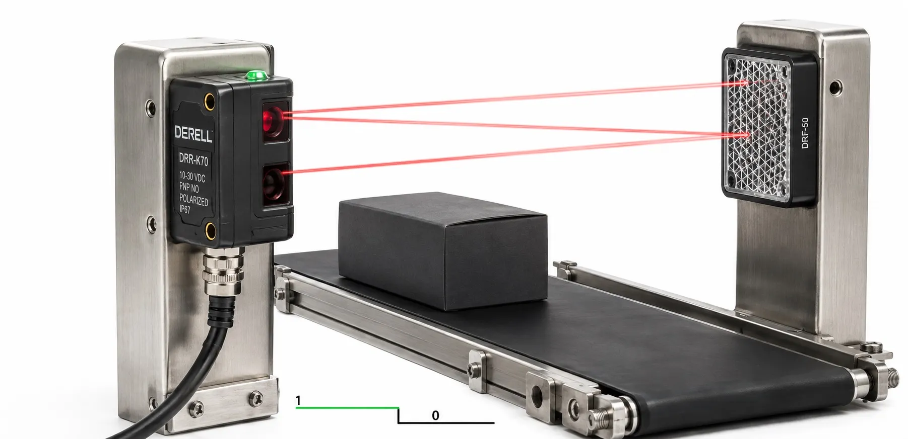
What is a retro-reflective sensor? How reflector-based photoelectric sensing works
A retro-reflective sensor is a photoelectric sensor with its light emitter and receiver in the same housing. It detects objects by monitoring light returned from a separate reflector mounted opposite the sensor. With no target in the beam, light reaches the reflector and returns to the receiver. When a target enters the light path, it reduces or interrupts the return sufficiently for the switching output to change according to the selected operating mode.
The reflector is part of the installation; the target does not need to reflect the light back. This type of sensor can detect moving or stationary objects. Suitability depends on object size, light attenuation, speed and mounting. Retro-reflective photoelectric sensors are used for box counting, product passage detection and, with suitable models, transparent packaging detection.
Retro-reflective, through-beam and diffuse: what is the difference?
Retro-reflective and through-beam sensors both detect a target by monitoring interruption or sufficient attenuation of a light path. The main difference is the arrangement of the emitter and receiver and the route taken by the light. Diffuse sensors instead evaluate light reflected by the target itself.
| Sensing method | Emitter and receiver | What is mounted opposite? | How is the target detected? |
|---|---|---|---|
| Retro-reflective | Same housing | Passive reflector | Interruption or attenuation of returned light |
| Through-beam | Separate housings | Electrically connected receiver | Interruption or attenuation of light travelling directly to the receiver |
| Diffuse | Same housing | The target to be detected | Evaluation of light returned from the target |
Consequently, “through-beam for moving objects, retro-reflective for stationary objects” is not a valid selection rule. Both can detect moving products when their specifications suit the application. Through-beam installations require electrical connections on both sides; retro-reflective installations require space to mount the reflector.
Why does the reflector matter? Range and small targets
The prismatic structure of industrial reflectors directs light back towards its source. An ordinary mirror cannot automatically replace the reflector specified by the manufacturer. Reflector type, size and optical structure must suit the sensor's light source and receiver. Red LEDs, infrared LEDs and lasers describe the light source; they do not, by themselves, define the sensing method.
Check which reflector was used to specify the operating range. A minimum sensor-to-reflector distance may also apply; operation at close range depends on the model and optical arrangement. This range specification does not mean that the sensor continuously measures the target's distance.
The smallest detectable object cannot be selected simply by looking at the visible light spot. The effective beam area, the proportion blocked by the target and the sensor-reflector geometry all matter. A larger reflector does not always improve small-object detection. Test actual targets, particularly when products are closely spaced.
What does polarization do? Detecting shiny surfaces
A polarizing filter helps distinguish light returned by a compatible reflector from misleading reflections off shiny targets. In a non-polarized arrangement, polished metal or glossy packaging may return light in place of the reflector, causing a target to be missed. Polarized retro-reflective sensors are used to reduce this risk.
Nevertheless, surface finish, target angle and material should be tested with actual products. Polarization and suitability for transparent-object detection are separate specifications. A transparent target requires a model designed for that application.
Can transparent bottles, glass and film be detected?
Models designed for clear-object detection can respond to small losses caused by absorption or changes in light direction, even when the beam is not fully interrupted. A standard retro-reflective sensor cannot reliably detect every transparent bottle or thin film. Whether a bottle is empty or full, its labels and its passing angle can change the result.
For models with teach-in adjustment, follow the manufacturer's required initial conditions and procedure. Some models learn the light returned from the reflector with no target present. If the sensor or reflector is replaced or moved, check the setting again and repeat teaching when required. A clean, stable and correctly aligned installation is particularly important here.
Some models provide contamination compensation, but this feature is not universal and does not eliminate the need for cleaning. Detecting the small light loss caused by transparent targets can require greater care with contamination and mechanical movement.
Advantages and application limits
Electrical connections on one side only are a useful advantage: the opposite reflector is passive. For opaque targets that sufficiently block the beam, detection can be less dependent on target colour and surface reflectivity than diffuse sensing. Non-contact detection avoids applying mechanical pressure to the product.
Excess gain describes the received-light margin relative to the level required for switching. A maximum range specified in clean conditions does not guarantee the same stability in a dusty or vibrating installation. A dirty reflector or poor alignment can reduce the return and cause false detection. Conversely, very high excess gain can make the small light losses produced by transparent targets harder to detect.
Response time, sensing range and cost vary by model. Retro-reflective sensors are not universally faster, cheaper or suitable for every harsh environment. Check the IP protection rating, operating temperature and compatibility with cleaning chemicals separately.
How do light-on, dark-on and PNP/NPN differ?
In light-on mode, the output becomes active when sufficient return light is received. In dark-on mode, it becomes active when the return falls below the threshold. In a conventional retro-reflective installation, an opaque target blocking the beam therefore activates a dark-on output. PNP/NPN selection describes the electrical output structure; it is a separate property from light-on/dark-on operation.
When reading an NO/NC designation, check the target and light conditions used as the manufacturer's reference state. Supply voltage, pin assignment and output type must match the PLC and its input module. Answer “What should the input do when a target arrives?” by considering both the wiring and the operating mode.
Conveyor example: checking speed for product counting
Assume a conveyor speed of 0.8 m/s and a centre-to-centre product spacing of 80 mm, or 0.08 m. If each product produces one pulse, the required counting frequency is f = v / p = 0.8 / 0.08 = 10 Hz. This spacing includes the product length and the gap, rather than the gap alone.
If the effective beam-blocking length in the direction of travel is 30 mm, the interruption lasts approximately t = 0.03 / 0.8 = 0.0375 s, or 37.5 ms. This is an initial estimate assuming a narrow beam and neglecting sensor delays. Measure the actual pulse width and compare it with sensor response time, input filtering and the counter's minimum high/low durations. Use a suitable high-speed counter input when required.
What should be checked during mounting and commissioning?
First verify compatibility between the sensor and reflector. Check the working range, secure both components against vibration-induced movement and align the beam with the reflector. Use the signal-quality indicator if provided. Follow the manual for teaching or sensitivity adjustment; an illuminated LED alone does not prove reliable detection of every product.
Test real products at the highest operating speed. Check different colours, shiny surfaces, labels, the fill state of transparent products and the smallest product gap. Follow the manufacturer's mounting guidance for nearby photoelectric sensors and strong ambient light. Select cables and connectors for the environment and maintenance needs, and keep the sensor face and reflector clean using appropriate methods.
If a reflector cannot be mounted opposite the sensor, consider diffuse sensing or a suitable fibre-optic sensor arrangement. Inductive sensors may suit metal targets, while sound-based ultrasonic sensors can be alternatives in some transparent-target applications. Check each method's target, distance and environmental requirements.