
what is pressure transmitter?
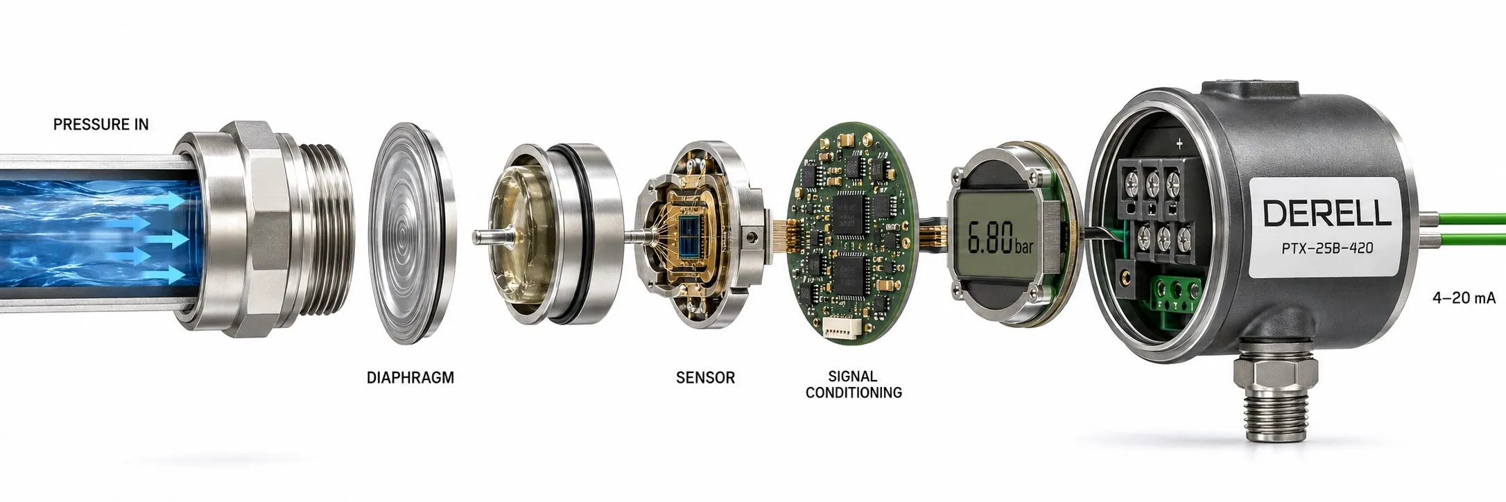
Turning process pressure into a usable measurement signal
A pressure transmitter measures gas or liquid pressure and converts it into a signal that another instrument can use. A PLC, display or controller can then read the measurement. Common outputs in industrial pressure instruments include 4–20 mA and 0–10 V, alongside digital interfaces on suitably equipped models.
What makes it a transmitter?
The term pressure sensor may describe either a sensing element or a complete instrument. A transmitter includes electronics that condition, scale and deliver the measurement. Manufacturers sometimes use “sensor”, “transducer” and “transmitter” differently, so the data sheet is more useful than the product name alone.
A pressure switch normally changes its output when a threshold is reached. A transmitter provides the measured value across its range, using an analog signal or digital data. An instrument may offer both. A switching output and a proportional measurement output serve different purposes.
How pressure becomes an electrical signal
Pressure slightly deforms a diaphragm or another elastic element. Piezoresistive and strain gauge designs detect a resistance change; capacitive designs detect a capacitance change. Electronics process this response and may apply temperature compensation or filtering. The measurement principle is only one part of suitability: wetted materials and operating conditions also matter.
Reading a 4–20 mA output
For a linear transmitter, 4 mA represents the lower range value and 20 mA the upper range value. The following example uses a 0–10 bar range. Correct interpretation of 4–20 mA or 0–10 V requires the receiving instrument to use the same scaling as the transmitter.
| Pressure | Ideal output |
|---|---|
| 0 bar | 4 mA |
| 2.5 bar | 8 mA |
| 5 bar | 12 mA |
| 7.5 bar | 16 mA |
| 10 bar | 20 mA |
For this example: Pressure (bar) = [(Current (mA) − 4) / 16] × 10. A 12 mA reading therefore represents 5 bar. For another linear range, multiply the fraction by the configured span and add the lower range value. 4 mA does not always mean zero pressure: on a −1 to 9 bar range it represents −1 bar.
A current loop still needs the right electrical design
The 4 mA live zero helps distinguish the lower measurement limit from some conditions such as an open circuit or loss of power. Actual fault indications depend on the transmitter and input configuration. A current reading inside the normal band does not, by itself, prove that the pressure measurement is valid.
Cable resistance can be accommodated within the available supply voltage and permitted loop load. A two-wire transmitter takes power and sends its measurement through the same loop; three- and four-wire arrangements may differ. Check the pressure indicator or PLC input type, whether it supplies loop power, the wiring diagram and the combined load. Current and voltage inputs are not directly interchangeable.
Specify the pressure reference as well as the range
Gauge pressure, on an atmosphere-referenced instrument, is measured relative to local atmospheric pressure. Absolute pressure is referenced to absolute vacuum. Differential pressure is the difference between two pressure points; differential pressure instruments can monitor filters and other process conditions. Matching the numerical range without matching the reference can still produce the wrong instrument choice.
The engineering unit also needs to match. Bar, kPa, MPa and psi are different units. A display can show an incorrect number even when the electrical signal is correct if its units or scaling do not agree with the transmitter.
Selecting for the actual process
Measuring range, overpressure rating and burst pressure are separate specifications. Surviving an overload does not establish measurement accuracy beyond the rated range. Consider pressure spikes, fluid and ambient temperatures, chemical compatibility, seals and process connections. The output, supply requirements and response time must also suit the installation.
Read how accuracy is stated: percentage of span and percentage of reading are different specifications. An error of ±0.5% of span corresponds to ±0.05 bar on a 0–10 bar instrument, but ±0.5 bar on a 0–100 bar instrument. Those figures describe that error component only; temperature effects and other contributions still need consideration. Compare instrument prices against the complete specification.