
what is laser sensors?
Laser sensors: choose the measurement, not just the light source
A laser sensor uses laser light to detect a target or obtain a measurement. The term covers several different jobs: presence detection, distance or displacement measurement, and, with suitable optics and processing, profile or 3D inspection. A laser in the housing does not mean that the device can reconstruct an entire object or identify all of its properties. [1] [2] [5]
Start by defining the information your machine needs. Is it a simple part-present signal, a distance in millimetres, or a cross-section containing many measured points? A photoelectric switch, a distance sensor and a profile scanner are not interchangeable, even when all three use a laser. Our sensor fundamentals guide provides the wider context. [1] [5]
A switching decision is not necessarily a distance reading
Laser photoelectric devices can use different beam arrangements. A target interrupts the light in through-beam sensing; a retroreflective arrangement monitors light returning from a reflector; a diffuse sensor receives light returned by the target itself. Laser describes the emitter, not one particular arrangement. [1]
A switching output might indicate that a target has crossed a taught threshold without sending a numerical distance to the controller. Some measuring sensors provide both distance data and programmable switching points. Check the actual interface and enabled functions rather than assuming that an illuminated target spot implies a measurement output. [4]
How the instrument determines distance
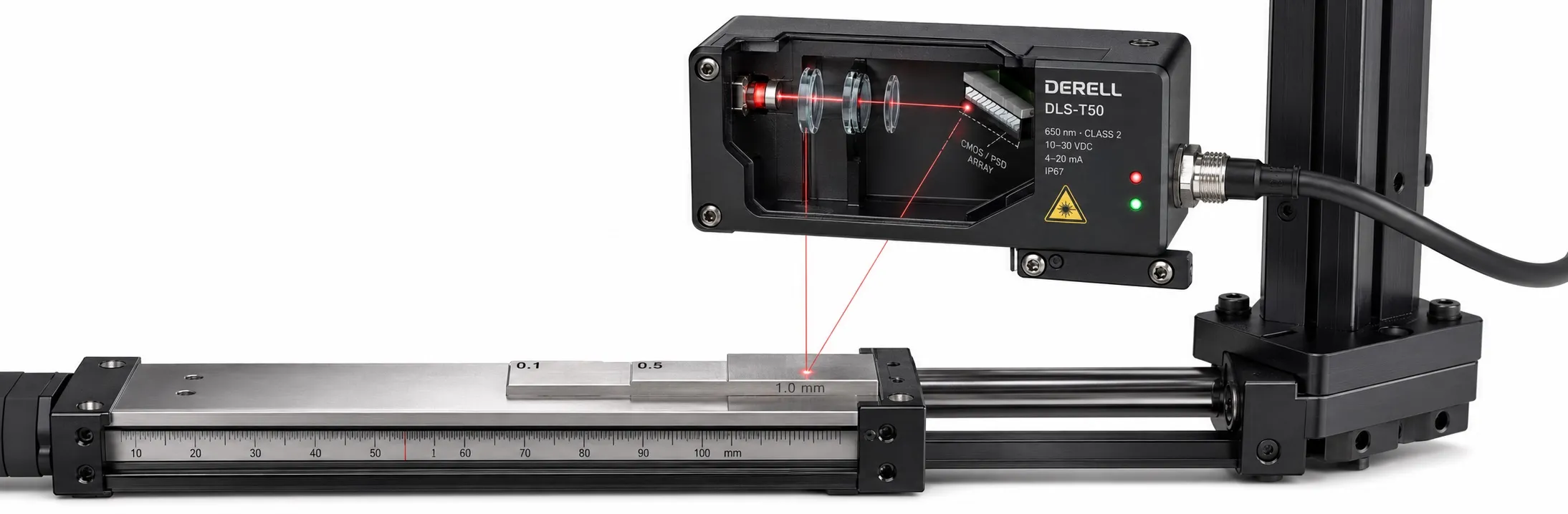
Laser triangulation is a geometric measurement. A receiving lens forms an image of the illuminated target spot on a position-sensitive detector. As target distance changes, the spot image moves. The instrument uses its known emitter–receiver geometry and calibration to convert that position into distance. It is not timing the round trip of an individual light pulse. [2]
Time of flight, or ToF, uses the propagation delay. For a pulsed round-trip measurement, the approximate relationship is d = c × Δt / 2. The factor of two accounts for the outward and return paths. This is a distance-measuring principle, not a “time-speed” sensor category. [3]
Timing example: Taking the speed of light in air as approximately 3 × 10⁸ m/s, a target 6 m away gives a round-trip time of about 40 ns. This simplified calculation concerns light propagation only. It does not establish the instrument’s update rate or mean that a new output value is available every 40 ns.
Phase-based ranging compares the modulation of transmitted light with the returning signal. The phase difference provides information about propagation delay and distance. Not every laser rangefinder directly times one isolated pulse. “Rangefinder” describes a purpose; it does not identify a unique measuring principle. [4]
A point, a profile and a point cloud are different outputs
A laser profile sensor projects a line and reconstructs a two-dimensional cross-section from its image. Controlled relative motion can combine successive profiles into 3D surface data. In a conveyor installation, encoder feedback can associate each profile with its position along the travel direction. One line profile is not a complete 3D model. [5]
Structured light projects a known pattern and evaluates how it appears on the surface. This does not require a laser: industrial systems also use blue LED fringe projection. Structured-light measurement therefore overlaps with, but is not confined to, laser sensing. [6]
LiDAR systems use light for ranging, but they are not all three-dimensional. A 2D scanner measures within a scan plane; suitable 3D systems combine measurements in different directions into a point cloud. Turning that data into object recognition or safe mobile-machine navigation requires additional processing and system design. [7] [17]
Decide what the PLC will receive
For a threshold decision, a compatible PNP or NPN output may be sufficient. A continuous measurement needs an appropriate analog input or digital interface. Depending on the model, options include 4–20 mA or 0–10 V, serial communication, IO-Link and industrial Ethernet. No single interface list applies to every laser sensor. Confirm units, scaling and data validity before using the value in the PLC. [12]
Worked height check: Suppose a fixed sensor looks perpendicular to a stable reference surface. The empty surface is 250 mm away, and the top of an opaque component measures 232 mm. Its height above that reference is 250 − 232 = 18 mm. This subtraction assumes that the sensor and reference remain in the same positions.
Height is not automatically thickness. If the component lifts off its support, one sensor above it includes that lift. Measuring between both faces may require a different arrangement. [8]
Invalid data is not zero distance. Handle a weak return, missing target or out-of-range value according to the instrument’s documented diagnostics. Do not mistake a held previous value for a fresh reading. Check NO/NC behaviour, switching direction and pin assignments against the model-specific instructions. Isolate the installation safely before changing connections. [15]
Read beyond the headline range and decimal places
Standoff and measuring span: An instrument may have a near region in which no measurement is available. A hypothetical operating interval of 80–120 mm has a 40 mm span; it does not measure from zero to 40 mm. Check both target-distance limits. [11]
Resolution, accuracy and repeatability: Resolution concerns the change that can be distinguished; accuracy concerns closeness to the true value; repeatability concerns agreement under repeated, specified conditions. A display increment of 0.01 mm does not establish a ±0.01 mm error limit. Read the linearity, temperature and test-condition specifications separately. [9] [10] [16]
Spot size and surface behaviour: Use the spot dimensions at the actual working distance. Dark, shiny and translucent targets can return different signals. If the spot straddles an edge, light from two surfaces can produce an unwanted mixed result. The smallest spot is not automatically the most stable choice; match it to the surface and the feature being inspected. [11]
Sampling and response: Measurement rate, output update rate and filtering are distinct. Averaging can smooth a fluctuating value while increasing response time. The switching or counting frequency of a photoelectric sensor is not interchangeable with the sampling rate of a distance instrument. [3]
Moving-target example: At 0.8 m/s with 2,000 valid, uniformly spaced samples per second, the spacing along travel is Δx = v / f = 0.4 mm. That is a sampling interval, not a claim of 0.4 mm accuracy or guaranteed detection of every 0.4 mm defect.
The target is illuminated. Why is the reading still unreliable?
With triangulation, both the outgoing path and the receiver’s view must remain clear. A slot wall can hide the returning light even though the laser spot is plainly visible on its floor. Dust, smoke, a dirty optical window, vibration and target angle can also disturb the reading. Check the geometry before increasing sensitivity. [8]
Include real production samples, expected surface variations, working distances and maximum operating speed in the acceptance test. Do not confuse an IP protection rating with a promise of permanently clean optics. Choose suitable mounting and protective accessories, and make the sensing-method comparison against the job rather than the appeal of the technology.
Laser classification is not a machinery-safety rating
The IEC 60825 family addresses laser product safety, including classification of accessible laser radiation. Read the class label and operating instructions. Do not stare into the beam or view it through optical instruments, and prevent specular reflections from reaching eyes. Colour and apparent brightness alone do not establish safety. [13] [14]
A Class 1 label does not make a sensor a personnel-protection device. An ordinary distance sensor or laser photoelectric switch is not a substitute for a safety laser scanner. Protective applications require suitable equipment, a risk assessment and a validated safety system. [13] [15]