
What is IGBT?
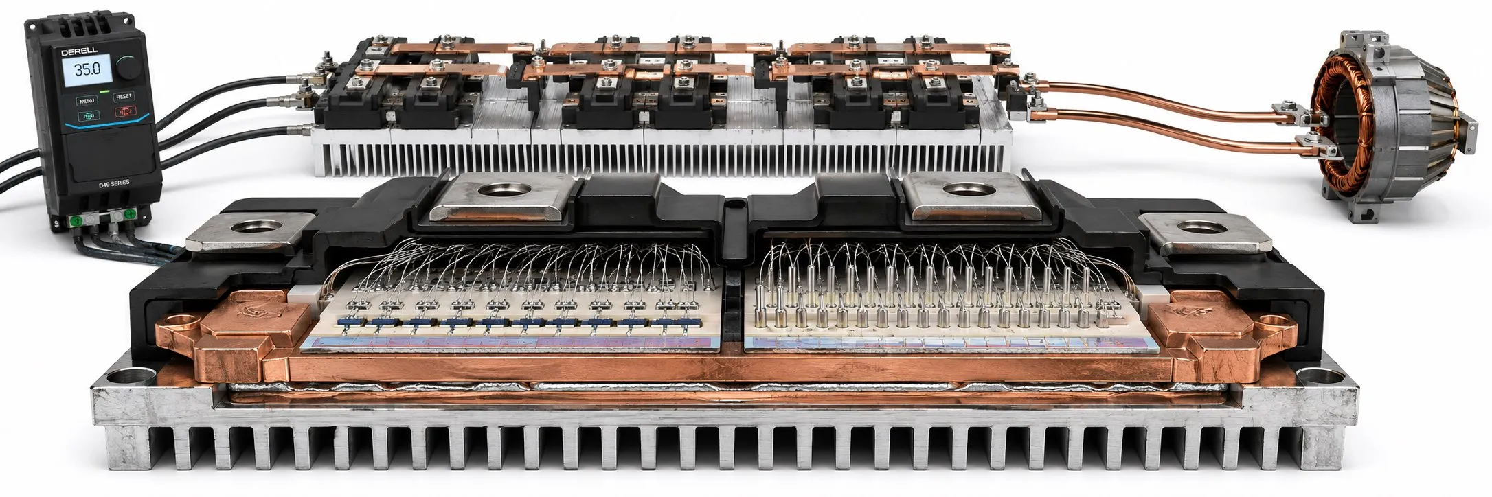
What Is an IGBT?
IGBT stands for Insulated Gate Bipolar Transistor. It is a power-semiconductor device used as a fast electronic switch in high-power converters and motor drives.
The simplest way to understand an IGBT is to think of it as an electronic power switch. It has no moving contacts. A signal applied to its gate controls a much larger power path between its collector and emitter.
This combination makes IGBTs particularly important in industrial variable frequency drives, servo drives, UPS systems, welding equipment and other power-electronic converters.
The three main IGBT terminals are:
G – Gate: control terminal.
C – Collector: one side of the main power path.
E – Emitter: the other side of the main power path.
An IGBT combines a MOS-controlled gate structure with bipolar conduction behaviour, which is why it can provide convenient gate control together with useful high-power capability.
How does an IGBT work? · IGBTs inside a VFD · Why do IGBTs get hot? · How is an IGBT checked? · FAQ
How does an IGBT work?
For a beginner, an IGBT can be viewed as a high-power switch controlled through its gate.
When the required gate-emitter drive voltage is applied, the device can be driven into conduction and carry current through the collector-emitter path. Removing the drive turns the device off and allows it to block voltage within its specified operating limits.
This switching can be repeated thousands of times per second, making the device well suited to PWM – Pulse Width Modulation.
The gate is not a simple mechanical control contact. It has capacitance, so the gate driver must repeatedly move electrical charge into and out of the gate during switching.
What does an IGBT do inside a VFD?
Inside a conventional VFD, the incoming AC supply is first rectified and transferred to the DC bus.
The inverter stage then uses IGBTs or another suitable power-semiconductor technology to rapidly switch that DC voltage and create the PWM motor output.
The simplified energy path is:
AC Supply → Rectifier → DC Bus → IGBT Bridge → PWM → Motor
A conventional three-phase, two-level inverter normally uses three half-bridge legs, one for each motor phase. Each leg contains an upper and a lower power switch, giving six main switches in total.
Why are there upper and lower IGBTs?
Each motor phase must be switched between different DC-bus states so that the complete three-phase bridge can synthesize the required AC motor waveform.
The upper and lower device in the same inverter leg must not be commanded on simultaneously. Doing so can create a direct DC-bus short circuit known as shoot-through.
Gate-driver circuitry therefore introduces a small dead time between switching events.
Is an IGBT a transistor plus a diode?
No. That is a common but misleading simplification.
An IGBT is a transistor device in its own right. However, motor windings are inductive and their current cannot change instantaneously, so many inverter IGBTs and IGBT modules include an anti-parallel freewheeling diode.
The diode provides an alternative current path during parts of the switching cycle. Infineon's IGBT documentation treats the anti-parallel diode as a separate device characteristic, and industrial IGBT modules are commonly specified with IGBTs and freewheel diodes together. :contentReference[oaicite:8]{index=8}
Why is the gate driver important?
The insulated gate requires little steady-state control current, but it has to be charged and discharged every time the IGBT switches.
If the gate is driven too slowly, the IGBT spends more time in its switching transition and switching energy increases.
If it is driven too aggressively, excessive dV/dt, dI/dt, ringing and EMI can become more difficult to control.
The external gate resistance, driver impedance and circuit layout therefore form part of the switching design. Infineon specifically describes gate resistance as one of the factors used to balance dV/dt, switching behaviour and noise. :contentReference[oaicite:9]{index=9}
Why does an IGBT get hot?
An IGBT is not an ideal zero-loss switch. Two important loss mechanisms are:
Conduction loss: while the IGBT is on, there is a collector-emitter voltage drop rather than a perfect zero-voltage path.
Switching loss: during turn-on and turn-off, voltage and current overlap for a short time and energy is dissipated on each switching event.
At thousands of switching events per second, these small energy losses become an important thermal load.
This is one reason why increasing carrier frequency can reduce audible motor switching noise while increasing inverter switching losses and thermal stress.
What is VCE(sat)?
VCE(sat) is an important on-state collector-emitter voltage parameter.
It must be interpreted under the current, gate-voltage and temperature conditions specified in the datasheet. Mitsubishi, for example, defines VCE(sat) at a specified collector current and gate voltage rather than as an arbitrary low-current multimeter reading. :contentReference[oaicite:10]{index=10}
It is therefore not reliable to judge IGBT ageing from one uncontrolled VCE reading alone.
What is gate charge?
Gate charge, Qg, describes the charge that has to be moved by the gate-drive circuit during switching under specified conditions.
A device with different gate charge can place a very different demand on the original gate driver even if its voltage and current ratings appear similar.
This is one reason replacement IGBTs should not be selected from only two headline numbers.
Important IGBT datasheet parameters
Depending on the application, engineers may need to compare:
VCES: collector-emitter voltage rating.
IC: collector-current capability.
VGE: permitted gate-emitter voltage.
VCE(sat): on-state voltage.
Eon / Eoff: switching energies.
Qg: gate charge.
Tj: junction-temperature limit.
RθJC: junction-to-case thermal resistance.
SOA / RBSOA / SCSOA: safe-operating limits where specified.
Short-circuit capability: where the manufacturer specifies one.
Why can the wrong replacement IGBT fail?
Two devices can share similar voltage and current markings while having different gate charge, switching losses, diode behaviour, thermal resistance and short-circuit characteristics.
A replacement should therefore be compared against the original datasheet and against the requirements of the gate driver, cooling system and switching frequency.
Why is cooling so important?
Heat generated in the semiconductor junction must travel through several thermal interfaces:
Junction → Case → Thermal Interface → Heatsink → Ambient
Mounting pressure, heatsink flatness, approved interface material and airflow all influence the final junction temperature.
A surface temperature measured with an infrared thermometer is not the same thing as junction temperature. Junction temperature normally requires a thermal model based on device losses and thermal impedances.
How is an IGBT checked?
Two very different questions are often mixed together:
1. Is there an obvious short circuit or open-circuit failure?
2. Does the device still switch correctly at its real voltage, current and temperature?
The first can sometimes be screened with suitable low-energy measurements after the equipment has been made electrically safe.
The second requires controlled power-electronics test equipment and cannot be proven by a simple multimeter check.
Before any measurement inside a VFD, the drive must be isolated according to the manufacturer's procedure and the DC-link discharge requirements must be followed. A VFD DC bus can retain hazardous voltage after mains power is removed.
In-circuit readings can also be influenced by the gate-driver network, freewheel diodes and other parallel components.
An obvious collector-emitter short, gate-emitter short or abnormal freewheel-diode short can indicate failure. Passing those static checks does not prove that the device is healthy under dynamic switching conditions.
High-energy switching characterization belongs on a protected laboratory fixture with suitable isolated instrumentation and the manufacturer's test conditions.
Does an overcurrent fault mean the IGBT is bad?
No.
An overcurrent trip can result from a damaged power stage, but it can also be caused by a jammed machine, short acceleration time, motor-cable fault, motor winding problem or incorrect motor parameters.
Use the OtomasyonAVM VFD Fault Codes section as part of the wider diagnosis rather than treating one fault code as proof of a failed IGBT.
IGBT vs MOSFET
Both are voltage-controlled power-semiconductor technologies, but their internal structures and operating characteristics differ.
MOSFET technologies are particularly attractive in many lower-voltage and higher-switching-frequency applications.
IGBTs remain widely used in industrial power converters where their voltage, current and conduction characteristics fit the application.
Modern designs can also use silicon-carbide MOSFETs, so device selection is an application decision rather than a universal “one technology is best” rule.
IGBT FAQ
Is an IGBT a relay?
No. It is a semiconductor power switch with no moving contacts.
Does the IGBT gate continuously consume current?
Very little steady gate current is required, but the gate capacitances must be charged and discharged during every switching event.
Does an IGBT have an anode and cathode?
The IGBT itself uses Gate, Collector and Emitter terminology. An anti-parallel diode, if present, has an anode and cathode.
Why is there a diode beside an IGBT?
It provides a freewheeling path for inductive motor current during parts of the switching sequence.
How many IGBTs are in a VFD?
A conventional three-phase two-level inverter commonly uses six main power switches, although actual topology and semiconductor technology can differ.
Why do IGBTs fail?
Possible causes include overcurrent, short circuit, overvoltage, excessive junction temperature, inadequate gate drive, shoot-through, poor cooling or excessive switching stress.
Does higher carrier frequency heat the IGBTs more?
It commonly increases switching losses because the devices switch more frequently, although actual limits depend on the drive and semiconductor design.
Can an IGBT pass a multimeter check and still be faulty?
Yes. A low-energy static test cannot demonstrate correct dynamic switching and thermal behaviour.
Related IGBT and VFD topics
Understanding VFDs · DC Bus · PWM · Carrier Frequency · VFD Fault Codes