
what is hall effect encoder?
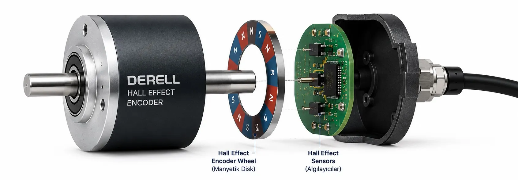
What is a Hall effect encoder?
A Hall effect encoder senses a moving magnet to provide feedback about shaft position, speed or direction. Its sensing elements respond to the magnetic field, so the magnet and sensor need no physical contact. The term “Hall effect” identifies how the encoder senses motion. It does not specify whether the device is incremental or absolute, or which electrical outputs it provides.
From a magnetic field to useful feedback
The Hall effect produces a transverse voltage in a current-carrying semiconductor exposed to an appropriately oriented magnetic field. A Hall sensor detects that response. An encoder adds a magnetic target, mechanical geometry and signal processing to turn it into motion information. A bare magnetic sensor is therefore not necessarily a complete encoder.
One incremental arrangement uses a multipole ring magnet on the shaft. Alternating north and south poles produce repeating output states. An absolute angle design can instead measure field components from a two-pole magnet and calculate its orientation. High output resolution does not always require a magnet with many poles. Also, magnetic sensing is a broader category than Hall sensing; other magnetic sensing technologies exist.
Incremental pulses or an absolute angle?
An incremental encoder reports changes as the shaft moves. One pulse channel can support speed measurement; direction requires additional information, commonly a second channel. An absolute encoder reports position within its measurement range. Single-turn absolute feedback tells you the angle within one revolution; it does not, by itself, retain the number of complete turns previously made.
A/B quadrature normally means two pulse channels separated by approximately 90 electrical degrees. That is a signal phase relationship, not a requirement to mount the sensors 90 mechanical degrees apart. A Z index may provide a once-per-revolution reference, but it is optional. Absolute devices may use a serial interface, PWM or an analog angle output, depending on the product.
How two channels reveal direction
A controller follows the order of the A/B states. The bits below are written as AB. Reversing shaft motion reverses the sequence.
| Channel relationship | AB sequence | Interpretation |
|---|---|---|
| A leads B | 00 → 10 → 11 → 01 → 00 | One direction |
| B leads A | 00 → 01 → 11 → 10 → 00 | Opposite direction |
A leading B does not universally mean clockwise. The viewing end of the shaft, wiring and controller settings determine the physical interpretation. During commissioning, check that actual movement agrees with the expected increase or decrease in the position count.
Four pole pairs: four cycles or sixteen counts?
Consider a simple ring with four pole pairs, producing one A/B cycle per pole pair with no electronic interpolation. Each channel produces four complete cycles per revolution. Counting only rising A edges gives four counts per turn. Counting every edge on both A and B gives sixteen counts per turn. The latter is x4 decoding; it does not mean that channel A produces sixteen pulses.
Check the manufacturer's definitions of PPR and CPR. CPR may refer to cycles or counts, depending on the document. A programmable encoder or interpolated magnetic design can offer an output resolution different from the physical pole count. Remember that resolution and accuracy are different specifications: a finer reported step does not guarantee a correspondingly accurate shaft angle.
Calculating speed without a factor-of-four error
If f is the complete-cycle frequency on channel A and P is that channel's cycles per revolution, then rpm = 60 × f / P. With 100 cycles per revolution and a measured frequency of 500 Hz, the shaft runs at 300 rpm. An x4 counter sees 2,000 counts per second at the same speed; use 400 counts per revolution in that calculation.
The mounting location matters too. An encoder on the motor side of a 10:1 reduction gearbox measures motor speed. A 300 rpm motor gives a theoretical 30 rpm output. If the task is simply to detect a stopped shaft or an underspeed condition, a speed monitor may be sufficient. Tracking position requires a different level of feedback.
Matching the encoder to a PLC or drive
Supply voltage and output voltage are separate specifications. A 24 V-powered encoder does not necessarily deliver 24 V signals. TTL, HTL, push-pull, open-collector and line driver outputs require compatible inputs. Differential A/A̅ and B/B̅ signals belong on an appropriate differential receiver. Follow the device documentation for pin assignments and any required termination.
Use a suitable high-speed counter or encoder interface. A standard PLC digital input may miss short pulses. Check both channel frequency and the interface's edge-counting capacity, including input filtering. An open-collector output may need a pull-up, either inside the receiving input or externally; its voltage and resistance must suit the circuit. Route cables and connect shielding according to the manufacturer's EMC instructions.
Where magnetic sensing helps—and where it needs care
In an optical versus magnetic encoder comparison, Hall sensing avoids dependence on a clean light path. That can help in contaminated machinery. However, tolerance of oil or dust is not an enclosure IP rating. External magnetic fields, ferrous debris, magnet eccentricity and an incorrect sensing gap can affect feedback. Temperature, vibration and sealing still need their own specifications.
A hollow-shaft encoder describes a mounting arrangement, not a sensing technology. A linear encoder measures linear travel; a “linear Hall sensor” can instead mean a sensor whose output is proportional to magnetic field strength. Resolvers and capacitive encoders provide other sensing approaches. Compare the requirements of the machine rather than choosing by technology name alone.
Useful starting points for troubleshooting
Counts disappear only at high speed: investigate input bandwidth, filtering and output drive capability with the actual cable load. An error repeats at the same shaft angle: examine magnet alignment, sensing gap and mechanical damage. Counts look correct but travel is wrong: check x1/x4 decoding, gear ratio and wheel circumference. These patterns guide investigation; they do not establish a diagnosis on their own.
A Hall effect current sensor may use the same physical principle, but it measures current and cannot replace an encoder. Across different sensor types, sharing a sensing principle does not make devices interchangeable.
Technical references: Texas Instruments — magnetic and optical incremental encoding · Texas Instruments — quadrature and pole pairs · Beckhoff — encoder interface configuration · Texas Instruments — absolute angle measurement · Dynapar — encoder technology overview