
What is grounding?
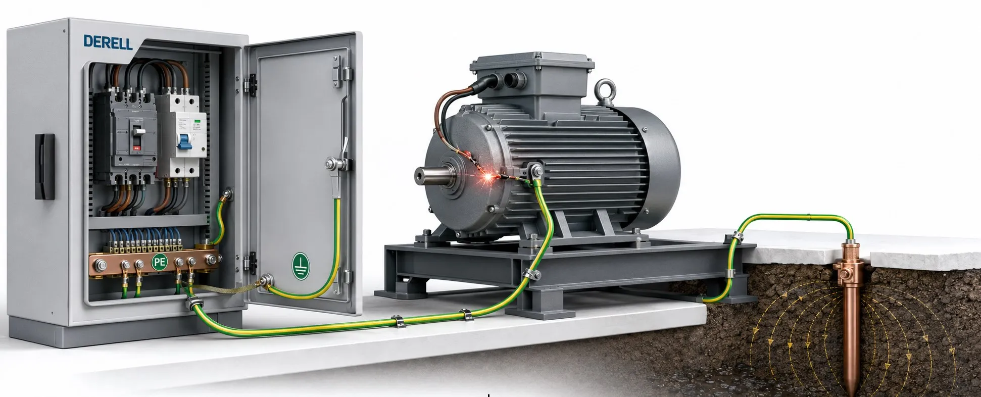
What Is Grounding? Protective Earthing, Bonding and Testing Explained
Grounding, often called earthing, establishes an electrical connection between designated points in an installation and the earth through suitable conductors and electrodes. Protective earthing forms part of the measures used to protect people when an insulation fault energizes an accessible metal enclosure. System earthing and functional earthing serve related but different purposes, such as controlling system behaviour, establishing a reference or supporting electromagnetic compatibility.
Grounding does not make electricity disappear, and it cannot hold every metal surface at zero volts under all conditions. Effective protection depends on protective-conductor continuity, equipotential bonding and protective devices that disconnect the supply within the required time. Installing a ground rod alone does not establish that an installation is safe.
How does protective earthing help prevent electric shock?
Imagine damaged insulation allowing a live conductor to touch the metal casing of a washing machine. If the casing has an intact protective earth conductor, or PE, a deliberate fault-current path already exists. In a correctly designed installation, the appropriate fuse, circuit breaker or residual current device disconnects the supply within the required time.
If the PE connection is broken, the casing may remain energized. A person touching it while also in contact with earth or another conductive surface can become part of the fault-current path. Protection should not depend on someone touching the faulty appliance. For the associated symptoms, see why an appliance casing can give an electric shock.
Fault current flows in a closed circuit back to its source. The return path depends on the earthing arrangement: it is mainly metallic in a TN system, while electrodes and the soil form part of the path in a TT system. Describing earth as a place where current simply vanishes misses this essential distinction.
Why is equipotential bonding necessary?
Equipotential bonding connects relevant conductive parts to limit dangerous voltage differences between surfaces that can be touched at the same time. Main protective bonding connects qualifying extraneous-conductive-parts, which may introduce an external potential, to the main earthing terminal. It does not mean indiscriminately connecting every metal object together.
A low electrode resistance is of little help to an enclosure whose protective conductor is broken. Conversely, bonding enclosures together does not by itself prove that all protection requirements have been met. The electrode system, protective conductors and bonding connections must be assessed together. See protective-conductor continuity and bonding resistance.
Protective earth, system earth, functional earth and signal ground
Protective earthing: This concerns accessible conductive parts that are not normally live but could become energized through an insulation fault. The PE connection on a Class I appliance is a familiar example. PE is not used as the normal load-current return, although protective-conductor current from filters can be present during normal operation.
System earthing: A defined point in the supply system, such as a transformer star point, is connected to earth to establish the intended operating and fault behaviour. This is a deliberate system design choice, not permission to ground arbitrary circuit terminals.
Functional earthing: A connection may be provided for measurement stability, interference control or electromagnetic compatibility. Serving a functional purpose does not automatically make that connection suitable as a protective conductor.
Signal ground or a 0 V reference: This is the reference against which circuit voltages are defined. A GND or 0 V terminal is not necessarily connected to the earth. A battery-powered or galvanically isolated circuit can float relative to earth. Connections between AGND, DGND, chassis and PE depend on the circuit architecture and equipment instructions.
Are neutral and earth the same thing?
Neutral, N, can carry current during normal operation. Protective earth, PE, serves an electrical protection function. A connection between neutral and earth at a designated point in the supply system does not justify linking them at an outlet.
Some arrangements combine the protective and neutral functions in a PEN conductor under defined conditions. An ordinary neutral conductor cannot simply be treated as PEN. Once N and PE have been separated, they must not be casually reconnected downstream. Incorrect links can place current on exposed metalwork and interfere with protection. See the difference between neutral and earth.
What do TT, TN and IT mean?
TT: The source has an earthed point, while the installation's protected metalwork is connected to its own earthing arrangement. Soil-path impedance can limit fault current below the level needed for rapid overcurrent-device operation, making RCD protection particularly important.
TN: Protected metalwork is connected to the source's earthed point through PE or, where permitted, PEN. The fault loop must allow timely protective-device operation. TN-S, TN-C and TN-C-S describe whether the protective and neutral functions are separate or combined in different parts of the system.
IT: The supply's live parts are isolated from earth or connected to it through a high impedance. Equipment still has protective connections. A properly designed IT system may continue operating after a first insulation fault under specified conditions, with insulation monitoring and fault investigation. Protection against a second fault is essential. IT does not mean an installation without protective earthing.
Is earthing still needed when an RCD is installed?
Yes. An RCD does not replace required protective earthing. It detects an imbalance in the currents passing through the circuit's live conductors. It may trip without PE, but a person touching a faulty enclosure could then provide the leakage path. That is not an acceptable substitute for an intact protective conductor.
A successful test-button operation does not verify electrode resistance or PE continuity. These require separate checks. See whether an RCD works without earthing.
What is an acceptable earth resistance?
There is no universal 1 Ω, 5 Ω or 10 Ω limit for every building, machine and installation. Acceptance depends on the earthing arrangement, protective devices, touch-voltage limit, disconnection time, application and applicable design requirements.
For an RCD-protected TT installation, a key relationship is RA × IΔn ≤ UL. RA represents the relevant electrode and protective-path resistance; IΔn is the RCD's rated residual operating current; UL is the applicable touch-voltage limit. Many general AC applications use 50 V; some conditions require a lower limit. Passing this equation alone does not establish compliance. Disconnection time and other requirements still apply.
For TN, a key condition is Zs × Ia ≤ U0: fault-loop impedance multiplied by the current needed for disconnection within the required time must not exceed nominal line-to-earth voltage. Ia is not necessarily the protective device's nameplate current. A low ground-rod resistance alone does not verify this loop.
What materials and electrode arrangements are used?
An earthing installation can include electrodes, earthing conductors, a main earthing terminal or bar, protective conductors, bonding conductors and suitable connectors. Electrodes may take the form of foundation arrangements, rings around a building, buried horizontal strips or deep-driven rods.
Foundation and ring electrodes can provide a distributed arrangement around a structure. Deep rods may be useful where suitable lower-resistivity soil layers can be reached. Selection depends on soil resistivity, moisture, seasonal changes, corrosion exposure, building construction and the design objective. Adding rods close together does not guarantee a reduction in resistance proportional to their number.
Copper, copper-bonded steel, galvanized steel or stainless steel may be appropriate in different applications. Material and conductor size require engineering selection for fault current, thermal and mechanical strength, corrosion and compatibility between dissimilar metals. A gas pipe or an incidental water pipe is not a substitute for the required protective conductor or a designed electrode system.
How is an earthing system checked?
Visual inspection: Look for missing connections, corrosion, loose joints, damaged conductors, unsuitable repairs and later alterations. An outlet with earth contacts may still have a missing or defective protective connection. Verifying earthing at an outlet requires more than checking its appearance.
Protective-conductor and bonding continuity: Suitable low-resistance testing assesses the connection between protected metalwork and the relevant protective terminal. A continuity beep from a general-purpose multimeter does not, by itself, demonstrate an adequate protective path.
Electrode resistance: The installation determines whether auxiliary-electrode, selective or clamp-based testing is appropriate. Stakeless clamp testing needs a suitable closed return path in a multiply earthed arrangement. It cannot be assumed valid for a lone electrode with no other return path. See resistance-to-earth measurement methods.
Fault-loop and protective-device tests: Depending on the system, verification includes fault-loop impedance, RCD operating time and other installation tests. An RCD tester provides information that the built-in test button does not. Test arrangements, including any temporary separation of protective connections, must be planned by competent personnel so that testing does not undermine installation safety.
A test screwdriver, an improvised lamp between line and earth, or touching an enclosure is not a valid earthing test. A multimeter reading close to nominal supply voltage between line and earth also does not establish that PE can safely carry fault current.
How often should it be inspected and tested?
The interval depends on installation use, environmental conditions, risk assessment and the applicable inspection requirements and maintenance plan. A home, factory, construction site and special installation should not automatically be assigned the same interval. Initial commissioning, significant alterations, repairs, flooding, lightning damage or suspicious faults may require additional verification.
A useful test record identifies the measurement point, test method, instrument, protective arrangement and acceptance criterion, not just an isolated resistance value. Comparing results over time can help reveal deterioration such as corrosion or loosening connections.
How does earthing relate to lightning protection and electrical noise?
Lightning protection brings together risk assessment, any required air-termination and down-conductor arrangements, earth termination, bonding and coordinated surge protective devices. Connection length and inductance matter during a fast lightning impulse; low-frequency resistance is not the whole story. Separate systems must be coordinated through a designed solution rather than casually connected or kept apart.
In automation and electronic equipment, cable screens, chassis, PE and signal references perform different jobs. A drive's motor-cable screen and an analogue sensor's shield should follow the equipment's EMC instructions. There is no universal rule that every shield must be connected at only one end or always at both ends. Never disconnect protective earth to cure interference. Consider appropriate screening, cable routing, bonding and signal isolation instead.
Common installation and maintenance mistakes
Linking neutral to earth at an outlet: This does not safely replace a missing protective conductor and can transfer hazardous potentials onto exposed metalwork.
Wetting the ground just before testing: A temporarily improved reading may not represent normal operating conditions. Adding salt indiscriminately can accelerate corrosion and create environmental problems. Permanent improvement requires an engineered assessment.
Switching or fusing the PE connection: This can remove the protective path. PE is not arranged as a normal load conductor that is routinely switched on and off.
Trusting wire colour or normal appliance operation: A green-and-yellow conductor is not proof of a sound connection. An appliance can operate normally with its protective earth disconnected.
Does every appliance need a protective earth conductor?
Class I equipment requires the protective connection specified by its design. Class II equipment relies on double or reinforced insulation and is commonly marked with a square inside another square; its protection does not depend on PE. A two-pin plug alone does not prove Class II construction. Check the equipment marking and manufacturer documentation, and do not modify its protective arrangement.