
What is a triac?
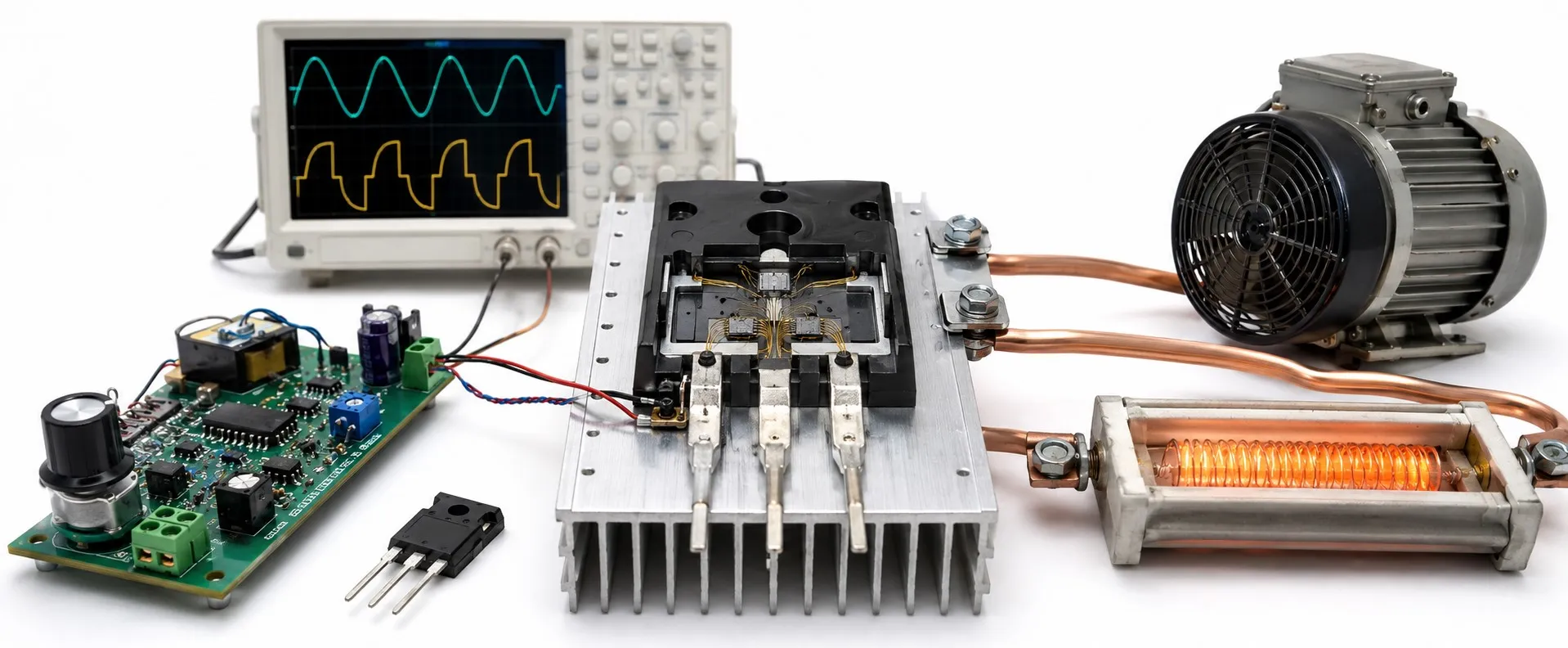
What is a TRIAC? How AC power control works
A TRIAC is a three-terminal semiconductor switch used in AC circuits. It can conduct current in both directions and belongs to the thyristor family. With suitable triggering, it can conduct during both the positive and negative half-cycles. Common applications include light dimmers, resistive heater power control and suitable motor control circuits.
What do MT1, MT2 and G do?
MT1 and MT2 are the main terminals carrying load current; some datasheets call them A1 and A2. G (Gate) is the trigger terminal. Gate current polarity and triggering conditions are assessed relative to MT1. TRIACs do not all share the same pin arrangement; check the manufacturer’s pinout rather than guessing from the package shape.
A microcontroller can determine the trigger timing. A suitable optocoupler, particularly an optotriac, can provide isolation between the control and power circuits. However, operation from a small control signal does not make a TRIAC gate circuit inherently isolated from the mains.
How does a TRIAC turn on and off?
A TRIAC is triggered by gate current of sufficient amplitude and duration. For conduction to continue after the gate pulse ends, the main current must have reached the latching current (IL). Once latched, the device turns off when the main current falls below the holding current (IH). Removing the gate signal does not directly turn off an ordinary TRIAC that has already latched.
In an AC circuit, current can approach zero each half-cycle, allowing natural commutation; conduction in the next half-cycle requires another trigger. With an inductive load, current and voltage may cross zero at different times. Describing turn-off solely in terms of the voltage zero crossing is therefore incomplete. On DC, a TRIAC can remain conducting while current stays above IH, so it is generally unsuitable for ordinary DC on/off control.
Phase angle control: Which part of the sine wave reaches the load?
With phase angle control, the circuit waits after the beginning of each half-cycle before triggering the TRIAC. An earlier trigger passes a larger part of the sine wave; a later trigger passes less. This changes the RMS voltage and average power delivered to a suitable resistive load. The mains frequency does not change.
Worked example: At 50 Hz, one half-cycle lasts 10 ms. A 5 ms delay in each half-cycle corresponds to a 90° firing angle. Assuming an ideal TRIAC and constant resistance, a heater consuming 1,000 W at full conduction receives approximately 500 W. With a 230 V supply, the load RMS voltage is approximately 163 V. Half the power does not mean half the voltage. Measuring this chopped waveform requires an appropriate True RMS instrument.
Traditional dimmers use an RC timing network, a capacitor and often a DIAC to establish the trigger timing. More advanced designs use integrated circuits or software for timing, zero-cross detection and protection functions.
Phase angle control versus burst firing
With burst firing, the controller passes a number of complete AC cycles and blocks others instead of cutting into each sine wave. For a heater with sufficient thermal inertia, passing 5 out of 10 complete cycles in a suitable time window can provide approximately 50% average power. This approach is found in some AC-output solid-state relay systems. Selection depends on the load and its effect on the supply network.
A zero-cross optotriac is used for on/off switching and complete-cycle control of suitable loads. A random-phase optotriac permits triggering at a chosen point within the half-cycle. A zero-cross driver cannot be treated as an interchangeable driver for unrestricted phase angle control.
Can it control every lamp and motor?
Resistive heaters and suitable incandescent or halogen lamps are common TRIAC-controlled loads. For LED lamps, the internal driver must support dimming, and lamp–dimmer compatibility matters. A mismatch can cause flicker, dropout at low settings or uneven dimming. An LED lamp is not automatically compatible with every TRIAC dimmer.
A suitable TRIAC circuit can adjust the speed of a brushed universal motor; feedback may be needed to maintain speed as the load changes. For an AC induction motor, most applications requiring a wide speed range with useful torque instead call for a suitable variable frequency drive (VFD). A TRIAC dimmer does not provide the function of a VFD. Some fan motors support voltage control, but this must be confirmed by the motor manufacturer.
How does it differ from a transistor, MOSFET or relay?
A transistor or MOSFET can be turned on and off through its control terminal under appropriate circuit conditions. An ordinary TRIAC instead exhibits latching behaviour after triggering. A diode primarily conducts in one direction, whereas a suitably triggered TRIAC conducts in either direction. An electromechanical relay uses mechanical contacts; a TRIAC has no moving contacts. However, a TRIAC can have conduction losses and a small off-state leakage current.
Which ratings matter when selecting a TRIAC?
Consider the IT(RMS) current rating, VDRM/VRRM repetitive blocking voltage, IGT gate trigger current, IL/IH, surge current and commutation capability. Triggering quadrant, ambient temperature, heatsink, package insulation and pinout also matter. A 16 A marking does not mean the device can carry 16 A without a heatsink under every operating condition.
With inductive loads or rapid voltage changes, a suitable RC snubber may be needed to reduce unwanted triggering or commutation problems. A varistor can limit voltage surges, while a correctly coordinated fuse provides overcurrent protection. A snubber, varistor and fuse do not replace one another; their ratings must be selected for the actual circuit.
How should a suspected TRIAC fault be assessed?
A load that stays on, never turns on or operates erratically may indicate a TRIAC fault, but the gate driver, connections and load can produce similar symptoms. A multimeter check on a de-energised circuit may reveal an obvious short; one measurement cannot verify every triggering and commutation characteristic. Inspect damaged components, heatsink contact and solder connections together. Disconnect power, verify the circuit is de-energised and ensure capacitors are safely discharged before testing.