
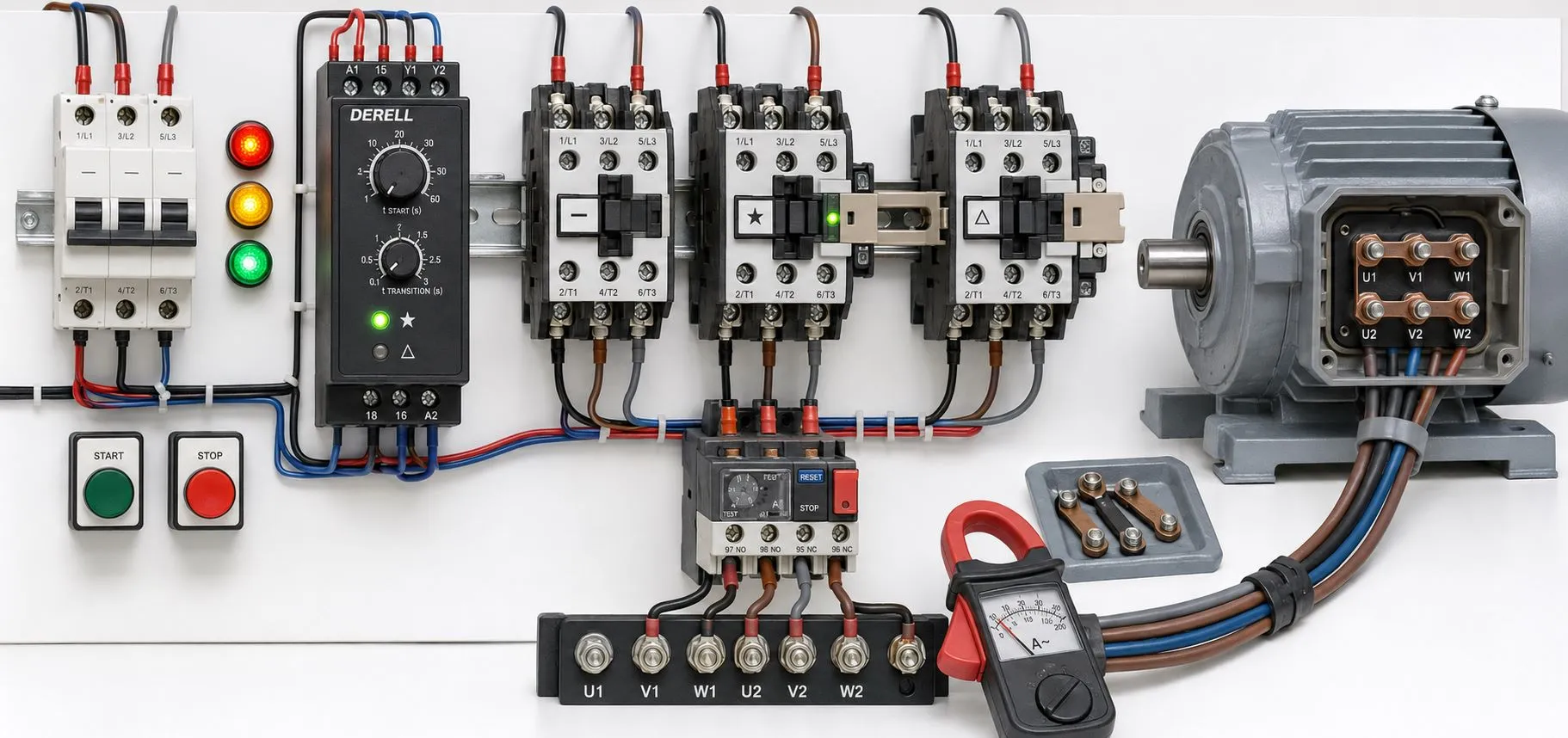
What Is a Star–Delta Timer Relay?
A star–delta timer relay manages the sequence that starts a suitable three-phase electric motor in star and then transfers it to delta for normal operation. The contactors switch the motor power circuit; the timer controls when their coils receive commands. Beyond the general operating principle of a timer relay, this application depends on the correct star-to-delta switching sequence.
Operating sequence: line, star and delta contactors
A conventional open-transition star–delta starter uses three contactors. In this explanation, K0 is the line contactor, KY is the star contactor and KΔ is the delta contactor. Actual manufacturers and project drawings may use different identifiers.
Line contactor
Star contactor
Delta contactor
Green: energized · Grey: released
The display loops every 8 seconds; these are illustrative intervals, not starter settings.
1. Stopped: K0, KY and KΔ are released. This starter circuit does not supply the motor.
2. Starting in star: K0 and KY are energized; KΔ is released. The windings are connected in star and the star starting interval runs.
3. Transition interval: K0 remains energized. KY releases and KΔ has not yet energized. The star and delta contactors are both released during this interval. The winding current path is interrupted; the rotor may continue turning through inertia.
4. Running in delta: K0 and KΔ are energized; KY is released. The motor operates in delta at the appropriate nameplate and supply voltage. A stop command or protection trip ends operation.
Releasing the line contactor during changeover is not part of this conventional sequence. KY and KΔ must never be energized together. This describes the operating logic; terminal wiring must follow the manufacturer's power and control diagrams.
Why does starting current fall, and why does torque fall too?
The difference between star and delta connections is the voltage applied to each winding. In star, winding voltage is line voltage / √3; in delta, it is line voltage. On a 400 V supply, each star-connected winding receives approximately 231 V, compared with 400 V in delta.
For the same motor, supply and speed conditions, the line current in star is approximately one third of the current with direct delta connection. Starting torque also falls to roughly one third. This current comparison is with direct delta starting under equivalent conditions, rather than with the motor's rated current. Extending the star interval may not solve a situation where the reduced torque cannot accelerate the load.
Can every motor use star–delta starting?
No. All six winding ends must be accessible, and the motor's rated delta voltage must match the supply. On a 400 V supply, a suitable motor marked 400/690 V Δ/Y can start in star and run in delta. A motor marked 230/400 V Δ/Y normally runs in star on that supply; changing it to delta would overvoltage its windings.
The motor's kW rating alone does not establish suitability. Assess its nameplate, terminal arrangement, load starting requirements and permitted starting duty together. Timer relay selection and installation must also match the motor and contactor arrangement.
How are the star time and transition interval selected?
The star starting interval depends on how the motor accelerates its actual load. Changing to delta too early can produce high current and mechanical shock. Keeping the motor in star too long can prolong acceleration with insufficient torque. There is no single delay suitable for every motor when choosing timer relay settings.
The transition interval is the period between star release and delta pickup. It is separate from the star starting time. Some timers provide a fixed interval; others allow selection. Assess it together with contactor opening and closing behavior, using a manufacturer-approved combination. A longer interval does not automatically give a safer or smoother transfer.
When designing a timing circuit, check the supply, reset interval, output sequence and coil load. Even when the timer's internal timing circuit works correctly, an unsuitable contactor or wiring error can disrupt changeover.
Timing does not replace interlocking or motor protection
Electrical interlocking prevents one contactor coil from receiving a command while the other contactor is active. Mechanical interlocking prevents simultaneous closure in a suitable star and delta contactor assembly. Do not rely solely on the time difference between relay outputs; provide the interlocks required by the manufacturer's circuit and accessory arrangement.
A standard star–delta timer is not a motor protection device. Consider a suitable overload relay, a phase protection relay where required, and coordinated fuses or a protective circuit breaker for short-circuit protection. Combined devices may include additional protection functions, but those functions must be confirmed from the actual model's specifications.
The overload setting depends on its circuit position. Protection measuring the complete motor line current uses a different setting from protection inside the delta loop measuring winding current. For the latter arrangement, approximately 0.58 × rated motor line current may apply. Final selection and adjustment depend on the manufacturer's diagram, protection characteristics and coordination.
How should common symptoms be interpreted?
The motor stays in star: Check the delta output, coil supply, auxiliary-contact interlock and delta contactor. An expired timer does not prove that the contactor has picked up. Timer relay troubleshooting should separate the control command from actual device operation.
Protection trips during changeover: Investigate star–delta overlap, incorrect winding connections, an unsuitable nameplate, insufficient speed before transfer or the switching transient. Increasing the protection setting and trying again is not a diagnosis. Verify the wiring and operating sequence first.
Contactors chatter or the timer resets: Examine coil voltage and voltage drop during the fault. An unstable motor or control supply can cause incorrect operation even when the timer itself is healthy.
How does it relate to PLCs, soft starters and drives?
A PLC can generate the same sequence, but software timing does not replace hardware interlocking. Timing in an automation system must be considered together with actual motor operation and protection signals.
A soft starter can regulate starting voltage electronically. A variable frequency drive controls frequency and voltage and also provides speed control. A star–delta timer does not control running speed; normal motor operation remains tied to supply frequency. Do not change the winding connection on a drive output using star–delta contactors unless the drive manufacturer explicitly approves that application.