
What are the power ranges used in DC drives?
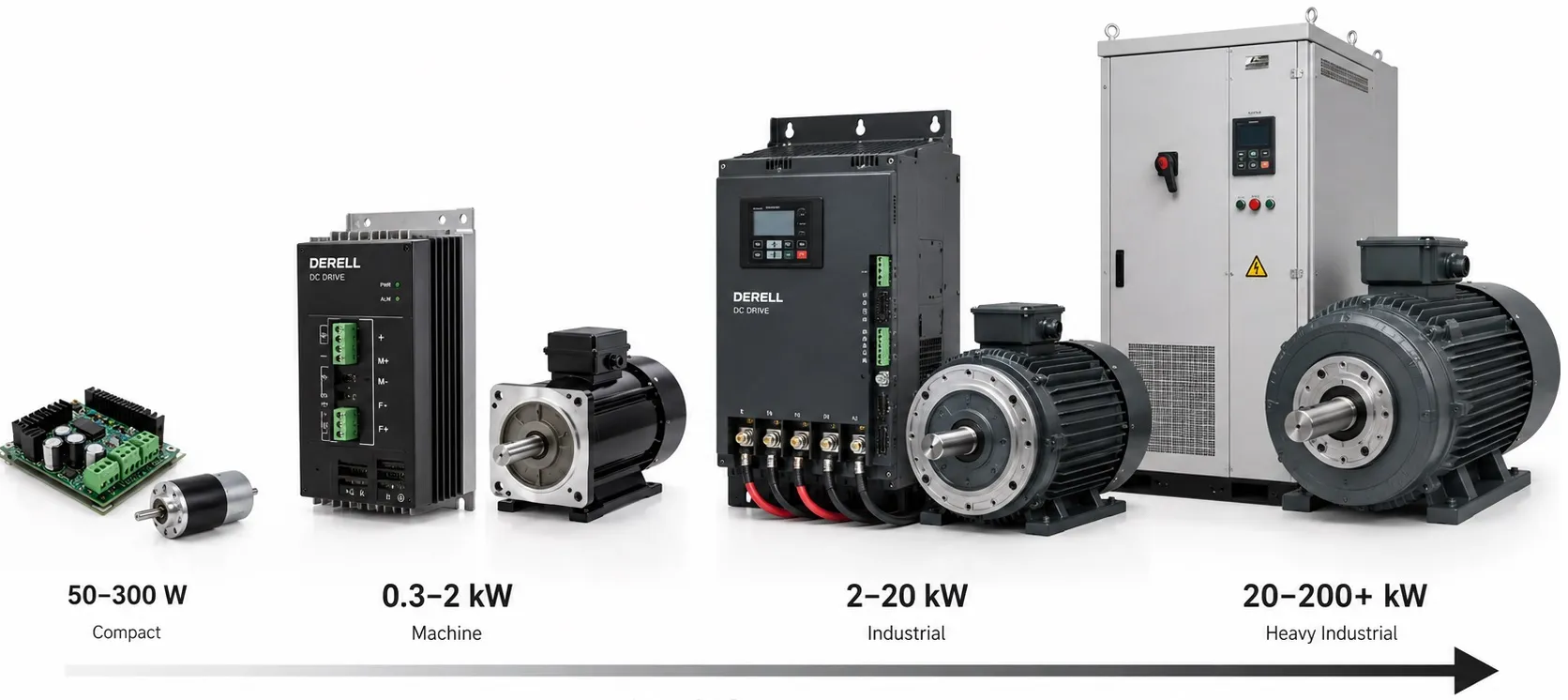
What power ranges are available for DC drives?
DC motor controllers cover applications from a few watts to industrial systems operating at megawatt scale. There is no single boundary that all manufacturers use to separate low-, medium- and high-power equipment. More importantly, a kilowatt figure alone does not tell you whether a drive can operate a particular motor.
For a useful comparison, read the power rating alongside output voltage, continuous current and overload duty. A controller built for a low-voltage battery system and a mains-fed industrial converter may have similar power figures while carrying very different currents.
A practical view of the available sizes
Below approximately 100 W: Small mechanisms, educational equipment and compact motion assemblies often use simple motor-control boards. Their operating voltage and continuous current are usually more useful than an advertised maximum wattage. Cooling conditions and the duration allowed at peak current deserve particular attention.
Approximately 0.1–5 kW: This scale can include small conveyors, feeding mechanisms, laboratory machines and auxiliary machine axes. Low-voltage PWM controllers are common, although other converter arrangements also exist in this range.
Approximately 5–200 kW: Examples include winding equipment, extruders, printing machinery, conveyors and certain machine-tool drives. Field excitation, speed regulation and braking requirements can become as important as the nominal power figure.
Above approximately 200 kW: Large process machinery, rolling-mill drives and high-power DC motor retrofits extend into this range. Suitable industrial converter systems can reach megawatt ratings. The upper limit depends on the product family and system arrangement rather than a universal definition of a DC drive.
These are illustrative bands, not standardized classes. A conveyor can fall into several of them depending on its size and duty. Likewise, choosing between drive types requires more than assigning the machine to a power band.
Check what the kilowatt figure actually describes
A motor nameplate normally states its rated mechanical shaft output. A drive specification may describe electrical output capacity or an associated motor rating under stated conditions. These quantities should not be treated as identical.
For reasonably smooth DC voltage and current, electrical power is approximately P = V × I. Dividing watts by 1,000 gives kilowatts. Where voltage and current have significant ripple, average electrical power is the average of their instantaneous product.
Consider a 10 kW electrical load. At 400 V it requires approximately 25 A; at 48 V it requires approximately 208 A. The power is the same, but the current requirement is very different. That changes the converter, cable sizes, terminals and protective fuse requirements.
Electrical power entering the armature does not all become useful shaft power. The DC motor has losses, and a separately excited motor also consumes field power. Converter losses and auxiliary equipment add to the total power drawn by the installation.
Continuous current matters more than a headline peak rating
A continuous current rating applies under specified cooling and environmental conditions. A peak or overload rating describes a higher current available for a limited duty. The two values answer different questions.
If a datasheet allows 150% current for a stated interval, the interval and recovery conditions are part of the rating. It does not mean the drive can operate continuously at that level. Repeated acceleration, frequent reversals or a heavily loaded start can make overload duty central to drive selection.
Built-in overload protection does not compensate for insufficient capacity. A drive that repeatedly reaches its current limit may fail to deliver the required acceleration or process performance even when it avoids immediate damage.
Low-speed operation can still require full current
Mechanical power depends on both speed and torque. A convenient relationship is P(kW) = T(N·m) × n(rpm) / 9550. At constant torque, reducing speed to one tenth also reduces mechanical output power to one tenth.
However, with approximately constant field flux, producing the same torque still requires approximately the same armature current. A low mechanical power reading at low speed does not necessarily mean a lightly loaded drive. This is why a high-torque, slow-moving mechanism cannot be sized from its momentary kilowatt output alone.
Motor cooling must also suit the duty. A shaft-driven fan may provide less cooling at reduced speed, so sustained loaded operation can require an independent blower and suitable temperature monitoring. A compatible PTC sensor can contribute to thermal protection.
Above base speed, field-weakening operation may reduce available torque. The motor’s operating curves and mechanical speed limit remain important. Where a wide speed range and precise regulation are required, the supported feedback options should be checked as well.
Power rating does not describe braking capability
Two converters with similar kilowatt ratings may handle deceleration differently. A regenerative arrangement can return energy to the supply when its topology and operating conditions permit. Other systems need a separately engineered way to manage braking energy.
A braking resistor is not a universal accessory that can be added to every DC drive. The converter must support the intended braking circuit. Frequent stopping, an overhauling load or repeated direction changes should therefore be described when specifying the equipment.
Allow for the real installation conditions
Ambient temperature, altitude and airflow can affect usable continuous current. Apply the manufacturer’s derating instructions where necessary. A nominally suitable unit may have insufficient capacity once installed in a hot or poorly ventilated enclosure.
Reactors, field supplies, cooling equipment and other supporting components also occupy space and generate heat. Their requirements belong in the system design rather than being added after the converter has been selected.
These considerations primarily concern conventional brushed DC motor drives. A BLDC motor needs electronic commutation appropriate to its construction. Matching voltage and kilowatts does not make a conventional armature-output converter compatible with a BLDC motor.
Prepare a useful motor and load specification
Start with armature voltage, rated armature current, shaft power and rated speed. For a wound-field motor, include field voltage and current. Then describe the load cycle, lowest and highest operating speeds, acceleration requirements and braking duty.
The resulting comparison should establish the required current at the correct voltage, for the intended duty and environment. A PLC, operator panel or communication option can improve machine control, but it does not increase the converter’s electrical capacity.