
Teco VFD fault codes
TECO VFD Fault Codes and Troubleshooting
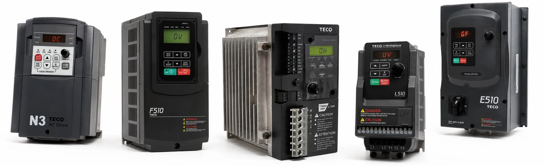
The fault codes below cover common problems found on TECO variable frequency drives. Before replacing the inverter, check the incoming supply, motor wiring, insulation, grounding and mechanical load.
OC – Overcurrent
Description: The inverter output current has exceeded the overcurrent protection level, approximately 200% of the rated inverter current.
Possible causes:
- Acceleration time is too short.
- An output-side contactor is being switched while the inverter is operating.
- The motor or load requires more current than the inverter can supply.
- Short circuit or ground fault in the motor circuit.
Check:
- Increase the acceleration time.
- Check the motor wiring.
- Check the motor and inverter ratings.
- Disconnect the motor and check whether the fault remains when the inverter is started without the motor.
SC – Short Circuit
Description: A short circuit or ground fault has been detected at the inverter output.
Possible causes:
- Short circuit or ground fault.
- Damaged motor insulation.
- Damaged or deteriorated motor cable.
Check:
- Check the motor wiring.
- Test the motor and cable insulation.
- Disconnect the motor and run the inverter again to see whether the fault remains.
GF – Ground Fault
Description: Ground current has exceeded the permitted level. The source information specifies approximately 50% of the inverter rated output current when the GF protection function is enabled.
Possible causes:
- Damaged motor insulation.
- Damaged motor cable.
- Current sensor (DCCT) fault.
Check:
- Check the motor insulation.
- Check the motor cable and terminals.
- Disconnect the motor and check whether the inverter can run without it.
- Measure the insulation resistance between the motor leads and ground.
- Reduce the carrier frequency if required.
OV – Overvoltage
Description: The DC bus voltage has exceeded the overvoltage detection level. The source values are approximately 410 VDC for the 200 V class and 820 VDC for the 400 V class, depending on the inverter and supply settings.
Possible causes:
- Deceleration time is too short and regenerative energy is returning from the motor.
- Incoming supply voltage is too high.
- Power-factor correction capacitors are connected in the motor circuit.
- High regenerative or braking load.
- Braking transistor or braking resistor fault.
- Incorrect speed-search settings.
Check:
- Increase the deceleration time.
- Check that the incoming voltage is within the inverter's rated range.
- Check the supply for voltage fluctuations or high-line conditions.
- Remove any power-factor correction capacitor connected on the inverter output side.
- Use the correct braking resistor or braking unit where required.
- Check the braking transistor and resistor.
- Review the speed-search parameters.
UV – Undervoltage
Description: The DC bus voltage has fallen below the undervoltage detection level, or there is a problem with the pre-charge circuit while the inverter is running.
Check:
- Measure the incoming supply voltage.
- Check the power input wiring and terminals.
- Check the supply for excessive voltage drop.
- Check the pre-charge circuit where applicable.
- If the supply and wiring are normal, the inverter control or power circuit may need inspection.
IPL – Input Phase Loss
Description: A phase loss or serious voltage imbalance has been detected on the inverter input.
The source parameter information states that this protection is active when 08-09 = 1.
Check:
- Check the incoming power connections.
- Check for loose terminal screws.
- Measure the voltage between input phases.
- Check for unstable or unbalanced supply voltage.
- If the incoming supply is correct and the fault remains, the input detection circuit may need inspection.
OPL – Output Phase Loss
Description: A phase loss has been detected between the inverter and motor.
The source parameter information states that this protection is active when 08-10 = 1.
Check:
- Check the U, V and W output connections.
- Check the output terminal screws.
- Check the motor cable and motor windings.
- Make sure the motor and inverter current ratings are suitable for the application.
OH1 – Heatsink Overtemperature
Description: The inverter heatsink temperature has exceeded the permitted level.
Check:
- Check the ambient temperature.
- Improve panel ventilation.
- Check that the cooling fan is running correctly.
- Replace the cooling fan if necessary.
- Reduce the carrier frequency if required.
- Check the motor load and inverter output current.
OH4 – Motor Overtemperature
Description: The motor temperature protection input has exceeded its trip level. This fault may be associated with the motor PTC temperature sensor.
Check:
- Check the motor temperature and ambient conditions.
- Check the mechanical load on the motor.
- Check the PTC sensor and its wiring.
- Make sure the MT and GND terminal connections are correct.
Related TECO Pages
TECO VFD Fault Code Pages