
About Siemens ET200 PLC
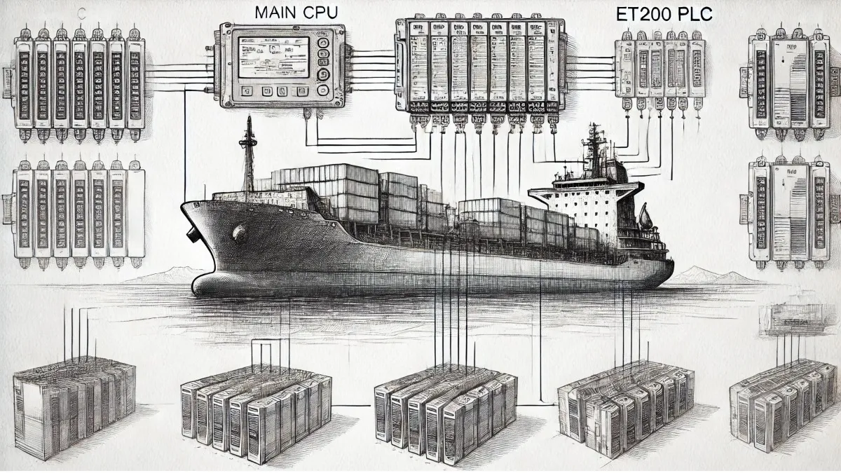
How field signals reach the control system
SIMATIC ET 200 is Siemens’ family of distributed input/output systems. Instead of running every sensor and actuator cable back to the main cabinet, signals can be collected at a station close to the machine. The station sends input data to a PLC over an industrial network and passes the controller’s output commands to connected equipment. ET 200 is widely used with SIMATIC S7. Integration with another controller depends on the selected interface and engineering support.
Editor’s note: Not every ET 200 station is a PLC. A conventional IM interface module handles station communication; it is not a CPU independently executing a user control program. However, ET 200SP stations with a CPU and certain other ET 200 configurations can run their own programs. Whether the logic runs in the main PLC or locally depends on the exact device and station configuration.
The main differences between systems
ET 200SP provides compact, modular I/O for cabinets with limited space. ET 200MP uses the S7-1500 module format and is an option for cabinet applications requiring high channel density. ET 200AL suits confined mounting spaces and moving machine sections; ET 200pro provides modular field installation; and ET 200eco PN offers block I/O for direct installation on the machine. In-cabinet and machine-mounted models have different protection ratings and connection arrangements.
ET 200S and ET 200M, often encountered during maintenance, are distinct systems within the family. Sharing the ET 200 name does not make their modules or bases interchangeable. Check the order number, hardware revision and firmware compatibility together when selecting a replacement.
Selecting input, output and power modules
Digital input modules read states from pushbuttons and switching sensors. Digital output modules can operate valves, interposing relays or contactor coils within their electrical ratings. Transistor and relay outputs are different: load voltage, per-channel current, group current and inductive-load protection must match the particular module’s specifications.
Analog input modules transfer measured values to the controller. 4–20 mA and 0–10 V signals require suitable channels and parameter settings; an analog module does not necessarily support both. Temperature measurements or special output functions may require dedicated modules. Signal type, wiring and software scaling must agree.
Do not assume that power supply modules and power distribution modules perform the same job. Electronics power and output-load power can be separate troubleshooting points. Terminal blocks and connection modules matter as much as the electronics. An ET 200SP BaseUnit must suit the installed module and potential group.
Counter modules handle suitable high-speed pulse applications, positioning modules support appropriate motion tasks, and other function modules provide application-specific capabilities. These options do not mean that every channel in a station offers the same speed or functionality.
Communication and where the program runs
Select the ET 200 communication interface for the installed network. PROFINET and PROFIBUS are different protocols and require the appropriate IM or CPU and physical connection. Support for other protocols must also be verified against the order number. An Ethernet socket does not imply support for every Ethernet-based industrial protocol.
For an interface-module station, the main engineering task is to configure the hardware in the controller project and match the module order, addresses and channel parameters. Integration may require a GSDML file for PROFINET or a GSD file for PROFIBUS; some devices are already included in the engineering tool’s hardware catalog. CPU-based stations additionally require a user program. Choose the TIA Portal or STEP 7 version according to the device generation and compatibility information.
A suitable IO-Link master module brings an IO-Link sensor’s process data, parameters and diagnostics into the system. IO-Link is a point-to-point connection between a master and a device, rather than a fieldbus replacing PROFINET. Connecting a sensor to an ordinary digital input does not, by itself, establish IO-Link communication.
A practical commissioning sequence
Start by comparing the complete part numbers and physical module sequence with the project. Check supply voltage, polarity, potential groups, shielding and grounding. Many stations use 24 V DC for their electronics, but load circuits require separate assessment. A single supply specification or −20 to +60 °C operating range cannot be assigned to the entire ET 200 family. Mounting orientation and loading conditions must also follow the particular device’s documentation.
For PROFINET, check the device name and network settings; for PROFIBUS, check the station address and bus termination. Compare input values with actual field states, then test outputs under controlled conditions after placing the machine in a safe state. An output command in the software does not prove that power reaches the load.
Separate the symptoms before replacing a module
If the whole station is missing, begin with power and network connections. If the station is accessible but reports a module fault, compare the order number, slot sequence and parameters. If only one channel fails, investigate field wiring, sensor power, channel type and the load circuit. Interpret LED names, colors and flashing patterns using the manual for the specific IM, CPU or module.
For example, if a conveyor sensor changes its input LED but the PLC tag remains unchanged, investigate data mapping and channel status. If the PLC output bit is active but a valve does not operate, check load power, output diagnostics and field wiring. These are fault-isolation examples; neither observation alone proves that a module is healthy or defective.
Do not assume every ET 200 configuration supports module replacement with power applied. Place the machine in a safe state first; hot swapping is permissible only under the conditions specified for the system and module. Before updating firmware, establish a project backup, version compatibility and any required revalidation.
Safety functions and used-product selection
PROFIsafe communication and fail-safe modules must be assessed together with a suitable safety controller, correct parameters and a validated application. Installing an F-module does not automatically make the complete machine safe. Forcing outputs or bypassing a safety function is not an appropriate troubleshooting method.
Some products offered through Otomasyon AVM are used equipment. Before purchasing, review the stated test condition, missing components and complete order number. Product inquiries should go to the store whose contact details appear on the product page. The relevant used items will not be restocked once sold out. Consult the ET 200 user manuals for selection and maintenance, and check that the existing ET 200 PDF document applies to your particular system and module.