6ES5 415-7AA11
Siemens 6ES5 415-7AA11 – 8-Channel 110/220 V AC Digital Output Module
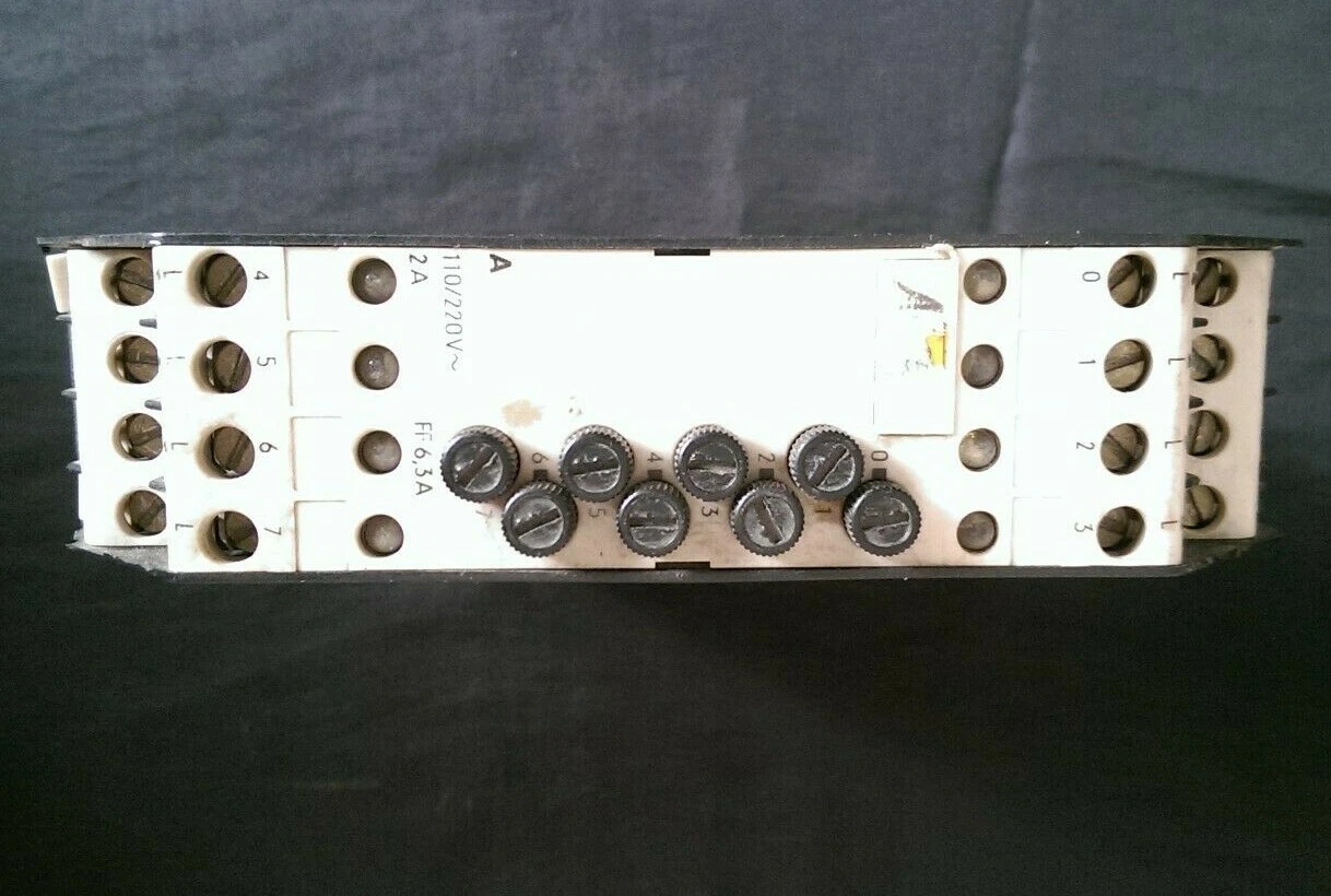
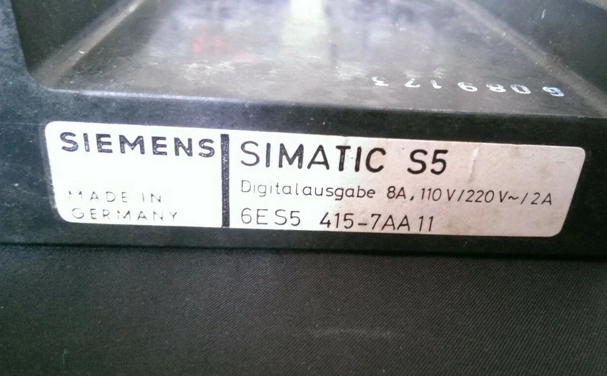
6ES5 415-7AA11 is a Siemens SIMATIC S5 card with 8 digital outputs, a 110/220 V AC nameplate marking and a 2 A rating per channel. This member of the S5 digital output range has channel markings 0–7 and an FF 6.3 A fuse marking on its front panel. The nameplate abbreviation “8A” means eight outputs; the current rating is separately marked 2 A.
The card belongs to the S5-110A/S generation of AC load control. Check the rack, sockets and wiring diagram of the existing SIMATIC S5 system together. Its placement in the S5 90/110 modules category does not establish compatibility with every system in that category.
AC load selection and channel current
110/220 V AC reproduces the manufacturer’s marking; it should not be read as a continuous 110–220 V operating range. Establish the voltage, holding current and pickup current of the control relay or contactor coil. Trace the CPU power supply and the output load supply separately on the installation drawing.
Triac outputs and off-state residual current
Siemens describes the 415 AC output family as triac-based. Internal RC elements can produce capacitive residual current when an output is off. Consequently, voltage measured at an unloaded output alone does not establish a fault; assess operation with a suitable load. Check that low-current loads actually release in the off state.
Field wiring and installation checks
Match the channel order, supply commons and terminal markings of the cables and connectors to the existing equipment drawing. Inspect protective grounding and insulation condition as well. Confirm pin numbers and any voltage-selection arrangement from a drawing for the 7AA11 revision.
Why an illuminated LED may accompany a dead load
The S5-110A manual explains that the LEDs on 410/415/417 output modules show the signal in the 5 V control circuit. An illuminated LED does not prove that load voltage is present or that the fuse is intact. Check the supply, fuse and load wiring together when a commanded output fails to operate its load.
Fuse rating and load rating
The front-panel FF 6.3 A marking specifies the fuse characteristic and current; the output remains in the 2 A load class. When inspecting a used output module, examine fuse holders, discoloration and previous repairs. Trace any load or cable short circuit before replacing a blown fuse.
Channel numbers and program addresses
Front-panel numbers 0–7 identify local output channels. The program byte address depends on the rack and socket arrangement. If the input/output address plan confirms output byte 3, for example, English STEP 5 notation may use Q 3.0–Q 3.7. This is an illustration, not a fixed address assigned to this card.
Records and backups before replacement
Back up the program and memory unit, and photograph the channel-to-terminal assignments. Record the interface module used for programmer access so that the connection can be reproduced during later maintenance. Preserve the existing address plan when replacing the output card.
Differences from similar order numbers
Siemens lists the 6ES5 415-7AA31 as 24/48 V AC, the 6ES5 415-7AB11 as 115 V AC, and the 6ES5 415-7AB21 as 220 V AC. Their voltage tolerances, residual currents and total-loading figures should not be transferred directly to the 7AA11.
The 6ES5 410-7AA11 belongs to the 24 V DC output family, while the 6ES5 417-7AA21 uses relay outputs. Compare the full order number, load voltage and wiring arrangement when selecting a spare.
Used-module inspection and channel testing
During S5 maintenance, test all eight channels individually with suitable loads and record both switching states. For used Siemens equipment, state the individual item’s label details, physical condition, included sockets and completed tests. Model information on this page does not establish an individual item’s tested condition or stock availability.
Editor’s note
Take a moment over the “8A” marking. It means eight outputs; each channel is in the 2 A class. A 6.3 A fuse marking does not raise the channel’s permissible load current.
Look beyond the illuminated LED. Check the load supply, the relevant fuse and the wiring to the coil. A correct control signal can still be accompanied by a break in the load circuit.
Use a suitable load before judging the triac. RC circuits in this family can make a meter display voltage on an unloaded output. Check both switching states under representative conditions.
A blown fuse deserves a cause check. Inspect the coil, wiring and holder before trying another fuse. Look for heat damage or loose contacts, and keep the specified fuse characteristic.
A couple of photographs can save a long search. Record the label, sockets and cable numbers, and save the program. Keep a short result for each of the eight channels so that the card’s condition is clear later.
OtomasyonAVM resources and PDFs
+ Shared SIMATIC S5 manuals and PDF archive
+ S5 digital output modules and model pages
Related topics
+ 6ES5 415-7AA31 – 24/48 V AC output module
+ 6ES5 415-7AB11 – 115 V AC output module
+ 6ES5 415-7AB21 – 220 V AC output module
+ 6ES5 410-7AA11 – 24 V DC output module
+ 6ES5 417-7AA21 – relay output module
Browse SIMATIC S5
+ Back to S5 digital output modules
+ Used Siemens products and models
Siemens and external references
+ Siemens S5-110A – 415 family, triacs and residual current, p. 1.7 (English)
+ Siemens S5-110A – meaning of output LEDs, p. 3.1 (English)
+ Siemens S5-110S/B – system and I/O family manual (English)
+ 6ES5 415-7AA11 manufacturer’s label – 8 outputs, 110/220 V AC, 2 A
+ 6ES5 415-7AA11 front panel – channels 0–7 and FF 6.3 A marking