6EV3053-0EC
Siemens 6EV3053-0EC — SIMATIC S5 Power Supply, 24 V DC / 5 V DC, 18 A
Siemens 6EV3053-0EC is a 24 V DC input, 5 V DC / 18 A output power-supply module used in older SIMATIC S5 systems. It belongs to the electronic supply arrangement of Siemens SIMATIC S5 equipment. When choosing this power supply, match the central unit’s connections and hardware requirements as well as voltage and current.
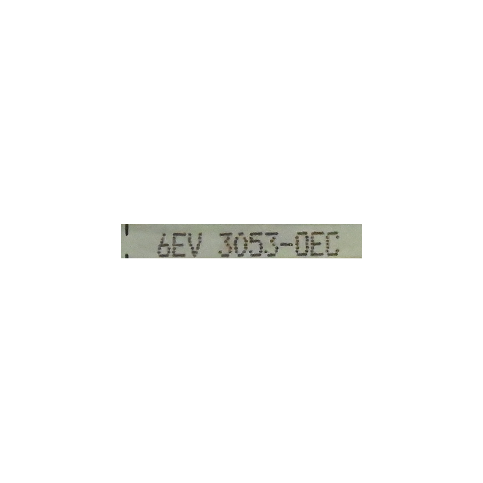
The model appears in our Siemens 6EV / 6EW directory and SITOP navigation group. Check the complete 6EV3053-0EC identification and revision marking. Do not automatically apply detailed specifications for 6EV3053-0DC or another suffix; similar connectors do not establish interchangeability.
24 V input, 5 V output and power calculation
The basic rating is 24 V DC input and 5 V DC / 18 A output. 18 A is the output current on the 5 V side. Measure input voltage and output current separately. Using nominal values, 5 V × 18 A = 90 W; this is a calculation for the 5 V output rail, not the module’s input consumption or losses under every operating condition.
Front panel and measuring points
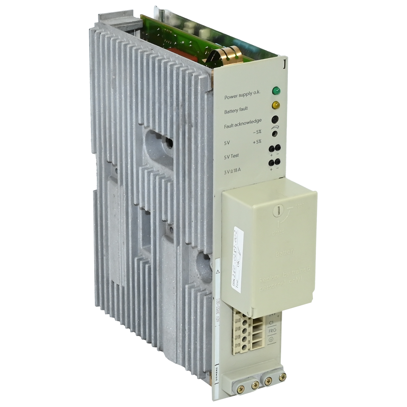
The inspected 0EC example has front-panel markings for Power supply o.k., Battery fault, Fault acknowledge, 5 V adjustment and 5 V Test. The adjustment area is marked −5% / +5%; this is not a guaranteed output-tolerance specification. A multimeter can read voltage at the test sockets; do not connect a load there. Establish rear power connections and connection accessories from documentation for the actual revision.
“3 V ≙ 18 A” identifies the scale of a current-monitoring measurement, not a separate 3 V power output. Its nominal correspondence is 1 V ≙ 6 A. Do not apply external voltage or connect a load to this point; use voltage-measurement mode. Calibration accuracy and monitoring behaviour require separate verification.
Voltage drop and loaded checks
Measure at the module test point and at the powered board under the same load. For example, 18 A through 0.01 Ω of connection resistance produces a 0.18 V drop and 3.24 W of heating. This calculation illustrates the importance of connector and cable contact. Check earthing and voltage fluctuations as well; do not arbitrarily increase the output setting to hide a poor connection.
By Ohm’s law, a 0.5 Ω load on 5 V draws approximately 10 A and dissipates 50 W. This is a partial-load example, not an 18 A capacity test. Use an adequately cooled electronic load or a resistor with suitable power margin. Verify output terminals, enable requirements and reference connections before independent testing.
Fault investigation and repair
Do not repeatedly apply power when an input or output short circuit is suspected. Isolate power, verify absence of voltage and narrow down the fault section by section. Match the actual hardware’s rating and speed class when replacing a fuse; no unverified fuse rating is assigned here to this complete 0EC order number.
Reasonable checks include capacitor ESR and capacitance, rectifier diodes, power components, connector solder joints and heated connections. These are general servicing suggestions, not confirmed recurring failures of this model. Allow for parallel circuit paths that can affect in-circuit measurements.
Battery warning and program protection
If Battery fault is indicated, assess the backup battery, connections and monitoring circuit using the relevant service procedure. First obtain readable backups of RAM contents, the program and required machine data. Removing a battery or interrupting power without establishing the correct sequence can cause data loss. Verify the exact battery spare part and replacement method for the installed hardware.
When buying a used power supply, request complete identification, revision, close-up connector photographs and the load and duration of any test. During Siemens S5 maintenance, record output voltage, load current, thermal condition and battery-warning status separately. An illuminated indicator or a no-load 5 V reading is not a sufficient test.
Editor’s Note
Keep the 18 A rating on the correct side. It belongs to the 5 V output. Assess input consumption, startup behaviour and cable losses separately when selecting the external 24 V source. Expecting 18 A at the input merely because it is printed as the output rating leads diagnosis in the wrong direction.
Pay particular attention to the 3 V marking. This point is not a small auxiliary supply. It is a current-monitoring scale; do not connect a load or external supply to it. Keep the meter lead in the voltage input, and avoid shorting the sockets with current-measurement mode.
Measure before adjusting a low 5 V reading. Compare the module and powered-board readings under the same load. Raising the setting to hide poor connector contact does not resolve the cause. Recheck after cleaning or repairing the connection, and record the initial setting.
Let measurements guide component replacement. Capacitors, rectifiers and heated solder joints are reasonable checks, but replacing everything at random is not diagnosis. Match electrical, thermal and mechanical characteristics of replacement parts, then increase the test load in stages and recheck.
Secure backups before starting at the battery cover. Protect the working program and machine data. Acknowledging a warning does not prove that the battery was replaced or that retention is healthy. Establish the correct cell and replacement sequence before removal; arrange data safety and isolate power for board repair.
Make the test record specific. If the trial was at 10 A, record 10 A rather than calling it an 18 A test. Include duration, input voltage and thermal observations. Power resistors become hot; voltage at measuring sockets alone does not prove that rear power connections carry the required load.
OtomasyonAVM Resources and PDF
Browse the 6EV3053-0EC model page, Siemens S5 main page and Siemens 6EV / 6EW used-model directory.
Siemens SITOP files — our common document page for this project.
Siemens SIMATIC S5-130 / S5-150 — Katalog ST 53, 1985 (German, reprint with 5.85 amendments, 144 pages, approximately 15.3 MiB). Manufacturer catalogue for family and system context. The supply table on PDF page 89 / printed page 8/3 is for 6EV3053-0DC; it is not a dedicated 0EC datasheet.
Documentation scope: A detailed manufacturer datasheet for the complete 0EC order number was not obtained. Front-panel details were checked against photographs of manufacturer-marked hardware bearing the 0EC code. Input tolerance, pin numbers, protection thresholds and the battery spare part require documentation for the actual hardware.
Related Topics
Related background: multimeter measurements, Ohm’s law, memory data loss and voltage fluctuations.
Browse Siemens S5 and Power Supplies
+ Siemens second-hand catalogue
External References
Siemens ST 53 — manufacturer catalogue archived by ADEGIS
Siemens 6EV3053-0EC — manufacturer-marked front-panel photograph (IndustryMall GmbH archive).