
Siemens Simatic CPU 90U
Siemens SIMATIC S5-90U CPU and Compact PLC System
The Siemens SIMATIC S5-90U is a compact PLC combining its CPU, power supply and onboard I/O in one housing. The 6ES5 090-8MA01 has 10 inputs for 24 V DC signals, 6 relay outputs and a 115/230 V AC mains connection. Within the SIMATIC S5 range, it is relevant to installed-machine maintenance, troubleshooting and spare controller selection.
This section covers the S5-90U. Review other S5 CPU families and CPU/central unit models on their respective pages. Sharing a system manual with the S5-95U does not mean that the two controllers have identical specifications.
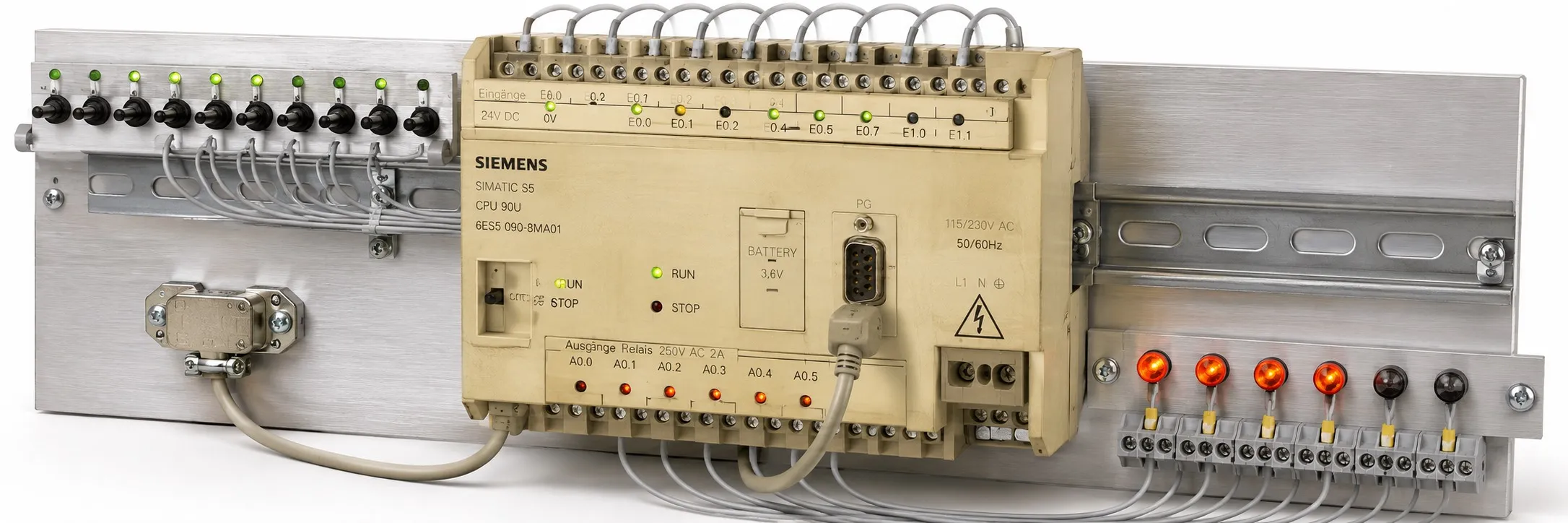
Distinguishing supply voltage from input voltage
The 115/230 V AC controller supply and 24 V DC input signals are different connections. A 24 V field circuit does not establish that the CPU itself requires a 24 V supply. When considering S5 power supplies for sensors or external modules, assess the controller supply and field-load requirements separately.
Onboard inputs and relay outputs
The ten inputs comprise 8 standard digital inputs, 1 interrupt input and 1 counter input. The latter two can also serve as standard digital inputs. For external digital input modules, check sensor type, common reference and signal level.
The six onboard outputs use relay contacts. As with external digital output modules, AC/DC load characteristics, inductive behaviour and switching frequency matter. Use the actual unit's nameplate and documentation covering its hardware version when assessing contact ratings; do not combine values from different editions.
The S5-90U has no onboard analog I/O. Analog measurement or control requires suitable S5 analog modules and verification of the applicable expansion conditions.
Program memory, battery and EEPROM
The S5-90U has 4 KB of user memory, equivalent to 2 K STEP 5 statements, with 32 timers and 32 software counters. This capacity must not be confused with the size of an installed memory submodule.
The S5-90U has no battery-low LED. Front-panel indications alone therefore cannot establish battery condition. Keep a verified application backup and a battery maintenance record.
Online saving to a suitable EEPROM uses the S5-90U's COMPRESS function in STOP mode. Verify the application and memory submodule before following the saving procedure in the manual.
Expansion through the IM 90
The S5-90U can be expanded through the IM 90 interface with up to 6 suitable S5-100U I/O modules. Select the interface module together with the expansion components. The six-module physical limit does not permit every combination: module type and power requirements must also be checked.
Use the complete order number when selecting from the S5 module categories. Listing a combined digital input/output board in the same product group does not, by itself, establish S5-90U compatibility.
Bus units form part of the connection between the CPU and external modules. Assess module coding, ribbon cables, terminals and mounting arrangements together. Check the individual S5-90U support of any special module, function module or positioning module.
PG connection and communications
The programming connection uses a 20 mA TTY physical interface; AS511 is the protocol. When selecting an S5 programming cable and adapter, verify electrical conversion and pin assignments. A standard RS232 cable is not suitable merely because its connector fits.
SINEC L1 operation requires suitable network hardware and configuration. Assess additional S5 communications modules according to their protocols and supported CPUs. S5-95U SINEC L2 or PROFIBUS options must not be presented as onboard S5-90U features.
Differences from the S5-95U
S5-95U models such as 6ES5 095-8MA01 and 6ES5 095-8MA04 are separate controllers. Compare supply requirements, onboard channels, program functions and communications before considering a replacement. A shared manual is not evidence of interchangeability.
Assessing a used controller
For used Siemens equipment, assess the complete order number, hardware version, memory submodule, terminal condition and documented tests together. To offer an S5-90U for sale, send the model, quantity, working/faulty condition, nameplate photograph and price to otomasyonavm@gmail.com. Sales require an invoice; used items are sold without returns. Equipment can be tested at the workshop.
Editor's Note
Start with the supply nameplate. Seeing 24 V beside the inputs is no reason to assume that the mains connection uses the same voltage. Match the complete controller code to its wiring documentation first.
An illuminated output LED does not prove that its relay contact is healthy. Worn contacts, loose terminals or intermittent operation under load can still be present. Assess whether the output controls its load correctly, rather than checking the lights alone.
Before changing the battery in a long-running machine, verify the program and data backup. A fitted battery is not proof of a working battery. A reliable backup today is much better than searching for a lost application tomorrow.
If a computer cannot connect, do not immediately blame the CPU. Check the adapter's TTY conversion, cable connections and software settings. A cable problem should not send a healthy controller to the faulty-parts shelf.
Where external modules are installed, test more than the CPU. Record the IM 90, bus connections and module order numbers as well. Matching a spare to the complete machine configuration is more valuable than seeing its RUN LED illuminate.
OtomasyonAVM Resources and PDFs
Identify the controller using the 6ES5 090-8MA01 technical page and SIMATIC S5 CPU family overview, then select the applicable document edition below.
+ S5-90U PDF files and manual archive
+ Siemens 6ES5 090-8MA01 data sheet — English
+ S5-90U/S5-95U System Manual — English, EWA 4NEB 812 6115-02b
The S5-90U scope of this system manual starts at 6ES5 090-8MA01, Edition 02. For earlier hardware, use documentation covering that version's wiring and addressing.
Related Topics
+ S5 interface modules and expansion connections
Browse SIMATIC S5
+ Used Siemens automation equipment
Siemens and External References
+ Siemens 6ES5 090-8MA01 data sheet — English
+ Siemens S5-90U/S5-95U System Manual — English
+ Siemens ST 50, 1998 — S5-90U mounting and expansion, section 2/3, English
+ Siemens GRACIS — AS511 and TTY connection, section 3.1.9, English