
Simatic S5 Racks
Siemens SIMATIC S5 Racks, Mounting Frames and Bus Units
Siemens SIMATIC S5 racks and mounting frames provide the mechanical support and backplane connections for CPUs, power supplies, I/O and interface modules. This section covers S5-115U/F/H central and expansion racks, bus units for smaller S5 systems, adapter casings and fan accessories.
Compare the complete order number, CR/ER designation, module positions and interface requirements when selecting a replacement. Not every physical slot accepts every module. A photograph of a populated rack does not establish that the CPU and other modules are included; confirm the supplied assembly for each product.
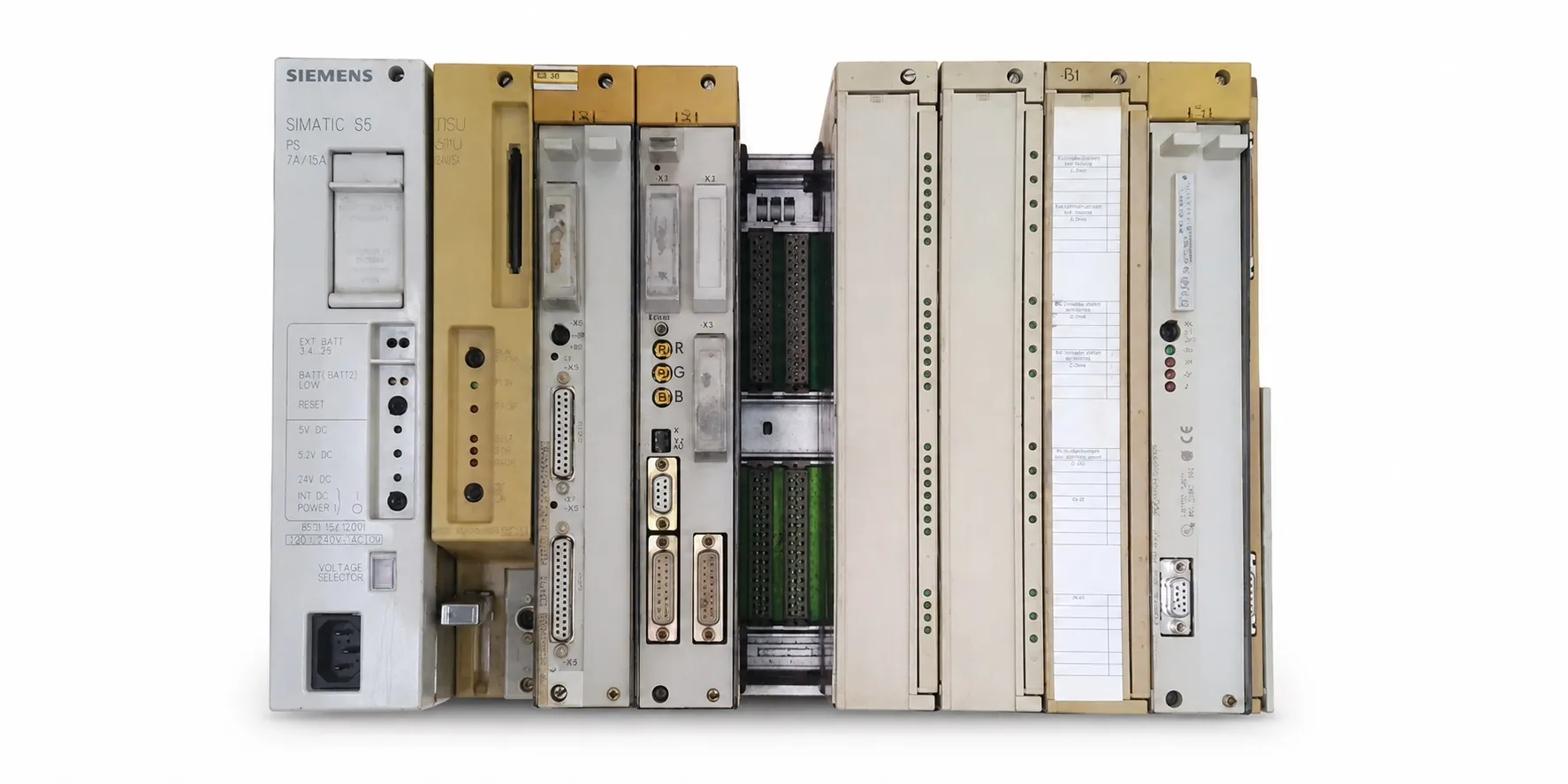
CR 700 central mounting racks
6ES5 700-0LA11 and 6ES5 700-0LA12 belong to the CR 700-0 central rack group. The 0LA12 provides four I/O module positions in addition to its power supply and CPU positions. The CR 700-0LB 6ES5 700-0LB11 requires its own module and adapter layout.
6ES5 700-1LA11 and 6ES5 700-1LA12 are CR 700-1 central racks. 6ES5 700-2LA11 and 6ES5 700-2LA12 belong to the CR 700-2 group. For the 1LA12 and 2LA12, the S5-115U manual specifies up to seven I/O modules; usable positions depend on module type, interfaces and system configuration.
Use the relevant slot diagrams for the CR 700-2LB 6ES5 700-2LB11 and CR 700-3 6ES5 700-3LA12. 6ES5 700-2LA22 is the CR 700-2F rack. Check the specific S5-115U, S5-115F or S5-115H configuration before assigning module positions.
ER 701 expansion racks
6ES5 701-0LA11 is an ER 701-0; 6ES5 701-1LA11 and 6ES5 701-1LA12 are ER 701-1 expansion racks. 6ES5 701-2LA11 and 6ES5 701-2LA12 belong to the ER 701-2 group, while 6ES5 701-3LA13 is an ER 701-3. Select the centralized or distributed expansion arrangement together with suitable IM modules, connecting cables and addressing.
The ER 701-3LH 6ES5 701-3LH11 is a special expansion rack for switched I/O in S5-115H systems. Its arrangement allows two central controllers to access a common I/O group. Follow the S5-115H diagram for IM 314R positions and termination.
S5 bus units: screw and crimp connections
6ES5 700-8MA11 is a bus unit with SIGUT screw-type terminals. 6ES5 700-8MA21 and 6ES5 700-8MA22 use crimp snap-in connections. These units provide bus and field connections as well as mechanical support. Check the terminal parts, module compatibility and side bus connections together.
6ES5 700-8FA11 with screw terminals and 6ES5 700-8MA22 with crimp terminals are enhanced EMC bus unit options. Preserve the required connection method and bus unit type. Similar dimensions or colours are insufficient evidence that bus units are interchangeable.
6ES5 700-8EA11 is a bus unit for Ex(I) I/O applications. It must be considered together with suitable Ex modules, separating components and installation requirements. Fitting an Ex bus unit does not make a standard module intrinsically safe.
Fan assemblies, mounting parts and adapter casing
6ES5 981-0HA11 is the long 115/230 V AC fan assembly; 6ES5 981-0HA21 is the 24 V DC version. 6ES5 981-0GA11 provides mounting parts for the long fan arrangement. Check the supply label, mounting dimensions and any fault contact connection.
6ES5 491-0LA12 is an adapter casing for applicable modules. The Siemens S5-115U manual lists this part as an accessory for the IM 314 and 313 watchdog module. Module capacity and dimensions specified for other adapter casings must not be applied to this part.
ET 200B terminal block
6ES5 700-2BA11 is an ET 200B TB1/DC terminal block with a legacy order number. It provides the terminal base for compatible electronics and serves a different purpose from a CR 700 central rack. Compare the terminal arrangement, fitted electronics and hardware version before replacement.
Inspecting used racks and bus units
Compare the model, quantity, working/faulty condition, nameplate photographs and price before requesting a quotation. The test scope should identify checks of the backplane, connectors, latches, terminal parts and fans. A bare rack and an assembly supplied with a power supply and modules have different delivery contents.
Editor’s note
Ask for more than a front photograph. Inspect the backplane, side connectors and module latches. A bent pin or loose connection can cause intermittent shutdowns even when the fitted modules are sound.
Distinguish a CR central rack from an ER expansion rack before purchasing. Physical fit alone is insufficient: the CPU, power supply and IM positions must match the system diagram. Photograph and record the existing module order before removal.
Read the fan supply label before applying power. 0HA11 is the AC version; 0HA21 is the DC version. Check noise, airflow and any fault contact as well as rotation. Worn bearings may become apparent during these checks.
Distinguish screw terminals from crimp connections on bus units. Missing terminal parts, broken side connections and contacts that fail to grip can complicate replacement. Ex installations also require the appropriate module and complete installation conditions.
Before installing a spare rack, compare the module layout, addressing and connection cables. Include the power supply, IM connections and termination in fault diagnosis rather than assuming that the rack is the only possible cause.
Agree the documented test scope and included parts before buying used equipment. Workshop testing is possible, with the scope determined by the hardware. All sales require an invoice; returns are not accepted. To offer S5 equipment for sale, send the model, quantity, condition, nameplate photographs and asking price to otomasyonavm@gmail.com.
OtomasyonAVM resources and PDFs
For system background, see About Siemens S5 PLCs, the SIMATIC S5 main page and S5 CPUs, central units and expansion racks.
Use the S5 system manuals and PDF files archive for mounting and connection diagrams. Check the model and edition covered by the document; S5-115U, S5-115H and S5-115F configurations require their appropriate diagrams.
Related topics
Review S5 power supplies, S5 interface modules, S5 cables and connectors and SIMATIC S5 CPU models when selecting a rack. The S5 module groups section provides routes to the relevant I/O and special function modules.
Browse SIMATIC S5
+ SIMATIC S5 | Siemens S5 PLCs | S5 module groups | Used Siemens equipment | All used equipment
Siemens and external references
+ S5-115U Programmable Controller Manual — EWA 4NEB 811 6130-02b; English.
+ S5-115H Programmable Controller Manual — EWA 4NEB 811 6111-02b; English.
+ S5-100U Programmable Controller System Manual — EWA 4NEB 812 6120-02b; English.
+ S5-90U/S5-95U System Manual — EWA 4NEB 812 6115-02b; English.
+ ET 200B Distributed I/O Station Manual — EWA 4NEB 812 6089-02c; English.
+ Siemens SIMATIC S5 Catalog ST 50 — ST 50, 1998; English; Siemens catalogue, external archive copy.