
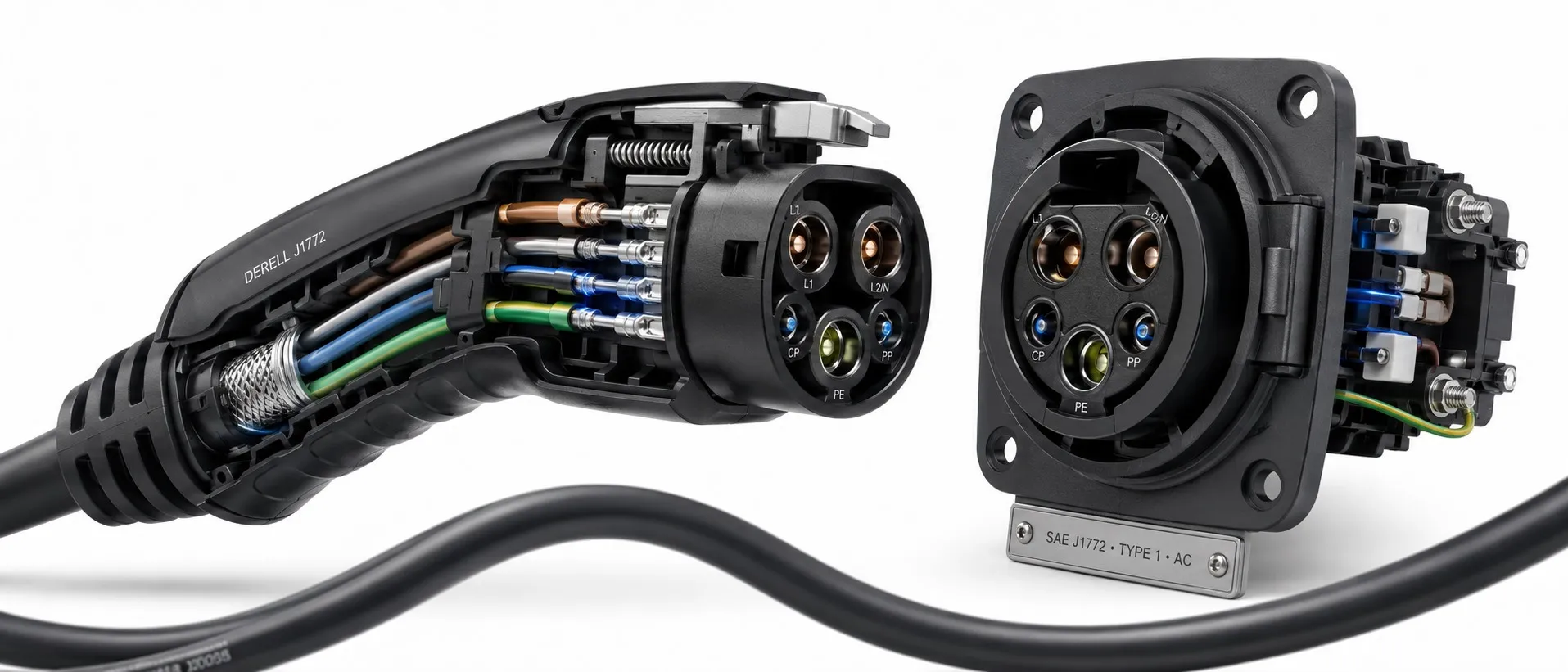
SAE J1772 Explained: More Than a Charging Plug
Drivers usually encounter J1772 as the name of a five-contact AC charging connector. Engineers use the designation for an SAE document covering the physical, electrical and functional interface between an electric vehicle and conductive charging equipment. Understanding that distinction makes it easier to separate connector compatibility from charging capability.
Within the wider landscape of EV charging standards, the familiar J1772 AC interface is commonly called Type 1. Type 1 also appears in the IEC 62196 connector framework.
Start with the Power Path
During Type 1 AC charging, the supply equipment delivers controlled AC power to the vehicle. The vehicle’s onboard charger, or OBC, converts that power into the DC required by the battery. This conversion location is central to the difference between AC and DC charging.
An AC wallbox manages the connection, communicates the available current and controls power delivery. It does not increase the onboard charger’s rating. A vehicle with a lower AC charging limit will still draw less than a higher-rated station can provide.
What the Five Contacts Do
Two power contacts carry the single-phase AC supply. They may be identified as L1 and L2/N because the second conductor’s role depends on the supply arrangement.
Protective earth, PE, provides the protective connection. Its function is part of the installation’s earthing system; it is not intended to carry the normal charging return current.
Control Pilot, CP, carries the basic charging-control signal.
The proximity or connection-sensing contact, sometimes labelled PP or CS, supports detection of the connection and latch condition. The Type 1 arrangement should not be confused with the resistor coding used to identify the capacity of detachable Type 2 cables.
How the Vehicle Learns the Available Current
Basic AC signalling uses a roughly 1 kHz Control Pilot waveform. Its PWM duty cycle advertises the permitted current, while changes in the vehicle-side electrical loading indicate connection and readiness states. The pilot is a control interface, not the high-power charging path.
A useful example: Within the 10%–85% duty-cycle range used for basic analogue current advertising, I = 0.6 × D, with D expressed as a percentage. A 50% duty cycle therefore advertises 30 A. Other duty-cycle ranges have different meanings or rules.
The advertised value is a ceiling. The station does not force that current into the vehicle. The vehicle can draw less according to its charger rating, battery conditions and charging controls.
Basic pilot signalling is also different from the higher-level communication associated with ISO 15118. A simple pilot waveform should not be assumed to report battery percentage or exchange payment information. In this context, PLC means Power Line Communication, rather than a programmable logic controller.
Level 1 and Level 2: Same Family, Different Supply Conditions
In North American usage, AC Level 1 is associated with a 120 V supply. AC Level 2 commonly uses 208 V or 240 V. The conventional Type 1 AC interface is single-phase, and the presence of the connector alone does not establish the equipment’s current rating.
The familiar upper Level 2 figure of 19.2 kW corresponds to 240 V at 80 A under suitable conditions. It is a capability of appropriately rated equipment, not a promise attached to every J1772 vehicle or cable. A connector’s marked voltage rating should also be distinguished from the nominal supply voltage.
For single-phase charging, active input power depends on voltage, current and power factor. With power factor close to one, P ≈ V × I provides a useful estimate.
32 A at 240 V ≈ 7.68 kW
32 A at 208 V ≈ 6.66 kW
The current limit is identical, but the available input power differs. Battery charging power is lower after conversion losses and auxiliary consumption are taken into account.
Keep kilowatts separate from kilowatt-hours. Adding 30 kWh to a battery at an average battery charging power of 6 kW takes approximately five hours. A changing average power changes the result; the connector name cannot determine the charging time.
The European 7.4 kW, 11 kW and 22 kW charging options introduce another consideration: phase count. Connecting a single-phase vehicle to equipment capable of three-phase output does not turn its onboard charger into a three-phase unit.
Where CCS1 Fits
A five-contact Type 1 AC connector has no dedicated DC fast-charging power contacts. A CCS1, or Combo 1, vehicle inlet adds two large DC contacts below the Type 1 portion. A suitable CCS1 inlet can accept its corresponding AC connector or a CCS1 DC connector.
A vehicle equipped only with a Type 1 AC inlet does not gain DC fast charging simply because CCS1 has a related upper shape. The required DC contacts, vehicle hardware and communication support must also be present.
Type 2 and CCS2 use different physical interfaces. When comparing Type 2 and CCS charging connectors, distinguish Combo 1 from Combo 2. “CCS” describes a charging system family, not a single universally interchangeable plug.
J3400/NACS Is a Separate Interface
SAE J3400/NACS is not a renamed J1772 connector. It is a different charging interface that supports AC and DC operation. Its growing deployment in North America makes it particularly important to identify the actual inlet on the vehicle and the connector offered by the station.
Adapters must be checked for connection direction, AC or DC service, electrical rating and manufacturer support. An adapter intended for J1772 AC charging is not a DC fast-charging adapter. Mechanical fit cannot supply a missing vehicle capability or guarantee access to every charging network.
What Compatibility Does Not Prove
Control and connection-detection functions help coordinate charging, but safe operation depends on the complete system: installation, protective conductors, cable ratings, switching devices and protective measures. IEC 61851 is a related international framework for conductive EV charging systems.
A J1772 compatibility claim does not, by itself, establish that every product contains identical temperature sensors or insulation-monitoring hardware. Selection of residual-current protection and other protective measures must follow the applicable installation requirements and equipment instructions.
For home charging, the sustained load and available supply capacity need assessment. If the cable cannot reach, adding an ordinary extension lead is not a substitute for a manufacturer-approved connection arrangement and suitable installation.
Publication History and the Wireless Charging Distinction
SAE records the original J1772 publication in October 1996. At the time this article was checked, the listed current revision was J1772_202401, January 2024. Describing 2009 as the first publication therefore misrepresents the document’s history.
Wireless charging belongs to a different technical subject. SAE J2954 addresses wireless power transfer and alignment for light-duty vehicles. It should not be presented as a feature introduced by a J1772 conductive-connector revision.
Technical references: SAE J1772_202401 · SAE J3400/NACS · SAE J2954 — Wireless Power Transfer · Texas Instruments — EVSE Control and Pilot Signals · U.S. Department of Energy — Charging Equipment