
Charging Standards for Electric Vehicles
Connectors, safety and communication must work together
Charging an electric vehicle requires more than a plug that fits the inlet. The electrical connection, safe power transfer, vehicle-to-charger communication and the operator's management system must work together. Standards for electric vehicles and charging systems address these different tasks. Some define connector dimensions, others specify protection and control functions, and others describe the exchange of digital messages.
Editor's note: Connector type, charging mode and charging power describe different things. Type 2 identifies a connector arrangement, Mode 3 describes a charging arrangement, and 22 kW is a power rating. The familiar five-contact Type 1/J1772 connector is for AC; CCS Combo 1 adds power contacts for DC.
Where does AC-to-DC conversion take place?
During AC charging, the vehicle's on-board charger converts alternating current into DC suitable for the battery. During DC charging, the main power conversion takes place outside the vehicle, while the vehicle and charger coordinate the voltage and current the battery can accept. The difference between AC and DC charging therefore concerns the location of the power electronics as well as charging performance.
Connector and charging-system families
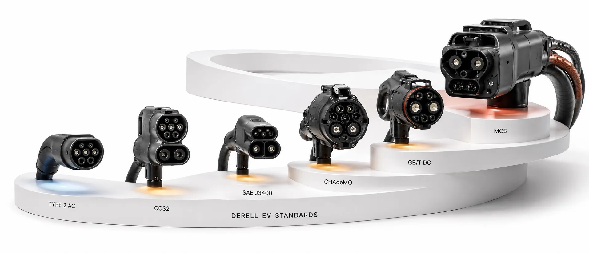
IEC 62196 addresses interfaces for plugs, socket-outlets, vehicle connectors and vehicle inlets. Part 2 covers dimensional compatibility for AC accessories, while Part 3 addresses DC and combined AC/DC interfaces. Type 1 is used for single-phase AC; Type 2 supports single-phase or three-phase AC with suitable equipment. A compliant connector alone does not establish compliance of the entire station.
SAE J1772 covers physical, electrical and functional requirements for a conductive charging arrangement developed for North America. In everyday use, J1772 often refers to the Type 1 AC connector. The scope of the standard and the capabilities of that connector are not identical: the combined coupler arrangement used for DC must be considered separately.
CCS — Combined Charging System brings AC and DC charging together around a combined vehicle inlet. Combo 1 extends the Type 1 arrangement, and Combo 2 extends Type 2, with additional DC power contacts. Type 2 and Combo 2 are common in European applications. CCS compatibility requires matching control and communication functions as well as a compatible physical connection.
CHAdeMO is a DC charging system and communication approach developed in Japan. It uses a different connection and protocol family from CCS. A CHAdeMO vehicle cannot be assumed to work with a CCS charger through a simple mechanical converter; the vehicle, charger and any approved adapter must be assessed together.
GB/T is a designation for Chinese standards, rather than the name of one connector model. EV charging interfaces, system requirements and communication are addressed in separate documents. For example, GB/T 20234.3 covers the DC charging coupler. Compatibility between a vehicle built for the Chinese market and another market's infrastructure cannot be established from appearance alone.
SAE J3400 / NACS is another system that belongs in a current overview. With the appropriate arrangement, the same two power contacts can carry single-phase AC or DC. It is particularly relevant to North American vehicles and infrastructure. Adapter selection must consider voltage, current, communication and manufacturer approval alongside the physical connection.
IEC 61851: safety, control and charging arrangements
IEC 61851 is a family of standards for conductive charging systems. IEC 61851-1 addresses general characteristics of the supply equipment, its connection to the vehicle and electrical safety requirements. A product described only as “IEC 61851 compliant” needs further clarification of the applicable part, edition and assessed scope.
Mode 1 describes a basic connection through a standard socket-outlet; Mode 2 adds an in-cable control and protection device; Mode 3 uses dedicated AC supply equipment and control; and Mode 4 uses an off-board DC charger. These modes do not map directly onto the North American Level 1 and Level 2 terminology. Installation conditions and local rules also determine whether a particular arrangement can be used.
IEC 61851-21-1 addresses electromagnetic compatibility requirements for on-board charging units, while IEC 61851-21-2 addresses EMC requirements for off-board charging equipment. These two parts replaced IEC 61851-21:2001. Describing them as general mechanical durability standards misrepresents their scope.
IEC 61851-22:2001 has been withdrawn. Its AC charging-station requirements were incorporated into IEC 61851-1:2017. A current specification should therefore not present Part 22 as an independent, current foundation standard for AC stations. Historical test reports must be read with attention to their dates and the editions applied.
IEC 61851-23 covers DC EV supply equipment requirements, while IEC 61851-24 addresses digital communication between that equipment and the vehicle to control DC power transfer. Calling these merely installation, testing and maintenance standards understates their scope. Power equipment and communication functions are distinct areas that operate together.
ISO 15118 and OCPP have different roles
ISO 15118 addresses high-level communication between the vehicle and charging equipment. Supported implementations can provide Plug & Charge, certificate-based authentication and exchange of charging information. ISO 15118-20 also defines messages for bidirectional power transfer. Supporting the standard does not automatically make every vehicle capable of exporting energy to the grid: compatible hardware, software, services and grid arrangements are also required.
OCPP is the protocol between the charging station and its charging management system, rather than the vehicle-to-charger protocol. Its role includes transaction management, status reporting, remote control and smart charging. OCPP 1.6, 2.0.1 and 2.1 are different versions; matching versions and the required functional support must be checked. OCPP support alone does not establish compatibility with every vehicle.
Implications for charging power and installation
Charging power is constrained by the station, cable, installation and vehicle. For example, a vehicle with an 11 kW on-board charger connected to a 22 kW AC point will charge at approximately 11 kW when the other conditions allow it. Comparing 7.4 kW, 11 kW and 22 kW charging requires checking both the number of phases and the vehicle's AC acceptance rating.
During DC charging, the advertised peak power is not maintained throughout every session. State of charge, temperature and battery characteristics affect the power that can be accepted. As a simple calculation, delivering 40 kWh at a constant 11 kW takes approximately 3.6 hours before losses; losses and changing power levels can extend the actual time. kW measures power, while kWh measures energy.
A safe installation requires coordinated consideration of residual-current protection, the effects of DC residual current, overcurrent protection, cable current-carrying capacity and grounding. A standard number on the equipment does not automatically establish that an existing installation is suitable. Product documentation and the installation design must agree, with assessment against applicable standard editions and local rules.
Related charging topics
Charging an electric vehicle at home brings supply-circuit requirements and everyday operating conditions together.
The difference between Type 2 and CCS explains why an AC connector and a combined DC inlet are not interchangeable concepts.
Wallbox versus a regular socket helps explain the control functions provided by dedicated charging equipment.
Charging an EV through an extension lead examines connection and overheating concerns.
EV charging frequently asked questions brings together further questions about vehicles and charging equipment.
Other topics connected with the infrastructure
Power supplies provide useful background on power conversion inside charging equipment.
Electrical fuses relate to overcurrent and short-circuit protection of the supply circuit.
Ethernet communication may connect a station to its management network; Ethernet and OCPP operate at different layers.
What is a kilowatt-hour? Distinguish charging power from delivered energy and consumption.
Solar energy and vehicle charging infrastructure considers planning solar generation alongside charging demand.