
Simatic S5 Function modules 2
Siemens SIMATIC S5 Function Modules 2
This section of the Siemens SIMATIC S5 function module range includes CPU 103, the IP 262 closed-loop controller, IP 264 electronic cam controller, CP 521 BASIC communications processor, a bus diagnostic module and interrupt-capable bus units. These products support maintenance, control and communication tasks, particularly in S5-100U and suitable small S5 system arrangements.
Select hardware using the complete order number, CPU version, module function, field connections and existing program. Products with similar housings in the Siemens automation range can perform different tasks. Identify the Siemens S5 PLC and its S5 module structure before choosing a part.
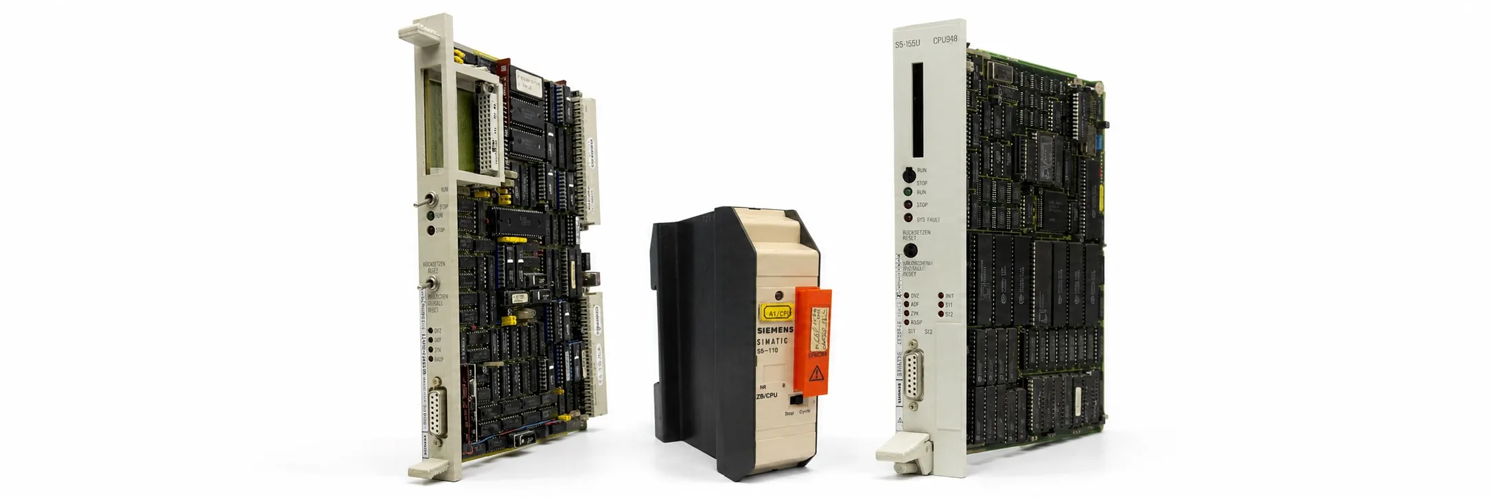
6ES5 103-8MA03 — S5-100U CPU 103
6ES5 103-8MA03 is the S5-100U CPU 103 processor. It uses a 24 V DC supply and has internal RAM specified for 10,240 statements. Statement count must be distinguished from memory capacity in KB. Compare hardware version and instruction support when reviewing other SIMATIC S5 CPUs.
Before replacement, back up the STEP 5 program, data blocks and DB1 parameters. Do not assume that the fitted S5 memory submodule matches the program running in RAM. Assess the battery indication and the ability to restore the program together.
6ES5 262-8MB12 — IP 262 S-type controller
6ES5 262-8MB12 is an IP 262 S-type closed-loop control module for applications with up to four control loops. The S-type arrangement has eight digital outputs for PDM pulse-duration control and step-action control. Its output arrangement differs from that of the 8MA12 K-type analog-output version.
For temperature, pressure and similar processes, assess the measurement signal and PID settings together. Verify the analog signal arrangement, sensor type and channel settings before changing controller parameters. Match the voltage and current requirements of the digital output load to the module’s ratings. Step-action regulation must be distinguished from stepper-motor control.
6ES5 264-8MA12 — IP 264 electronic cam controller
6ES5 264-8MA12 is an IP 264 electronic cam controller. It switches outputs according to the position of a linear or rotary axis and supports up to 64 cams on 16 cam tracks. Assess incremental and suitable SSI absolute encoder connections against their interface requirements.
For packaging, press and transfer applications, check encoder direction, reference position, the cam table and the relationship between outputs and actual motion. Other S5 positioning modules can perform different tasks. Read encoder supply and signal level separately, and prepare the cables and connectors using the correct pin assignment. Preserve cam and parameter data before removing the module.
6ES5 521-8MB12 — CP 521 BASIC
6ES5 521-8MB12 is a CP 521 BASIC communications processor. It can perform data-processing and serial-communication tasks through its own BASIC program. It provides RS-232C/V.24 and TTY connections; the manual specifies 110–9600 baud for the bidirectional interface. Do not assume identical hardware and programming to a CP 521 SI version.
Match baud rate, character format, cable wiring and the BASIC program to the connected equipment. When reviewing S5 communications processors and interface modules, a physically matching socket is insufficient. Establish separately whether the delivery includes the memory submodule, program and connecting cable.
6ES5 330-8MA11 — BUS SIGNAL DISPLAY diagnostic module
6ES5 330-8MA11 is a diagnostic module with LEDs for the local I/O bus supply and control signals. It does not read field inputs, drive output loads or provide normal I/O data to the PLC program. Observe bus indications together with the CPU’s RUN/STOP state.
Assess supply indicators separately from data and control indicators. Record the station, bus unit and operating state used for the observation. Related service equipment is listed under S5 supplementary modules and test hardware and S5 special modules.
700-8MB11 and 700-8MB21 — interrupt-capable bus units
6ES5 700-8MB11 has SIGUT screw terminals, while 6ES5 700-8MB21 uses crimp snap-in connections. Both are interrupt-capable bus units with two I/O module positions. Two positions do not mean two input channels; channel count and electrical ratings depend on the fitted modules.
For interrupt operation in S5-100U: use CPU 103 version 8MA02 or later, place the bus unit directly beside the CPU at slots 0 and 1, and fit suitable four-channel input or comparator modules. The CPU must be in RUN, OB2 must be programmed, and interrupts must not be disabled by the program. The same bus unit in a later position can operate as a normal bus unit.
Check the fitted digital input module together with the interrupt requirements. Inspect crimps, screw terminals, ribbon bus connections and the mounting arrangement. Successful normal I/O communication alone does not establish that the interrupt path works.
Addressing, supplies and module compatibility
Addressing example: in S5-100U, a module using an eight-byte address window, such as IP 262, uses 64–71 / 40H–47H at slot 0 and 72–79 / 48H–4FH at slot 1. This does not establish one addressing method for every module. Distinguish a diagnostic module, a bus unit and a module exchanging program data.
Check the internal bus supply, external 24 V supply and output load supply separately. Assess S5 power-supply capacity alongside the installed module loads. For combined I/O modules and special-function boards, identify terminal functions from the module’s own diagram.
For CPU 944/945/948, coordinators and other larger-system components, review S5 CPUs and system hardware. Do not match small-system modules to large rack-system components solely because both belong to SIMATIC S5.
Used equipment purchasing and selling
For a quotation, provide the complete model, quantity, working or faulty condition, label photograph, hardware version, included accessories and asking price. Send details of equipment you wish to sell to otomasyonavm@gmail.com. Sales require an invoice; used equipment is sold without returns. Workshop testing may be arranged when a suitable system is available.
Editor's Note
Identify the function first: a CPU, IP controller and CP communications processor perform different jobs. Similar front connectors do not establish the same function. Read the complete label.
For IP 262, distinguish 8MA from 8MB. An analog output and a pulse-duration output place different requirements on the controlled equipment. Establish correct sensor measurement before changing PID settings.
For IP 264, look beyond encoder pulse count. Supply, signal type, direction and reference position matter too. Preserve the cam table and parameters before removal; fitting a replacement does not restore machine settings automatically.
For CP 521 BASIC, the program matters alongside the hardware. Test serial communication using the cable, character format and working BASIC application together. A TxD LED alone does not complete the test.
If interrupts fail, check the CPU version, first two slots, fitted input module and OB2 before blaming the bus unit. Normal input operation does not validate the complete interrupt arrangement.
Interpret diagnostic LEDs in relation to the operating state. A few illuminated indicators do not establish a sound system. Record the CPU, bus unit, cable and test performed so that the fault can be investigated consistently.
OtomasyonAVM Resources and PDF Manuals
+ Shared Siemens SIMATIC S5 PDF archive
+ S5-100U operating/system manual — English
+ SIMATIC S5 ST 50 catalogue — English
+ IP 262 control module manual — German
+ IP 264 electronic cam controller manual — English
+ CP 521 BASIC manual — English
+ COM DB1 parameterization manual — English
Related Topics
S5 analog modules · S5 positioning modules · S5 communication modules · S5 cables and connectors
Browse SIMATIC S5
Parent S5 module category · SIMATIC S5 CPU options · S5 CPUs and system hardware · S5 supplementary modules · Siemens S5 PLCs
Siemens and External References
+ S5-100U System Manual — CPU 100/102/103 (English)
+ IP 264 Equipment Manual (English)