
Phase Protection Relays
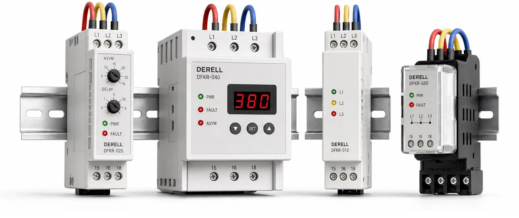
Monitoring and controlling a three-phase supply
Phase monitoring relays check supply conditions in three-phase electrical systems and signal faults to the control circuit. They are commonly considered for pump, compressor, fan and machine panels using induction motors. The correct model depends on supply voltage, required monitoring functions and the control circuit. Devices sold under the same general description do not necessarily monitor the same faults.
Editor's note: A marking such as 5 A or 8 A does not mean that a motor drawing that current can be connected directly. It describes the output contact rating under specified conditions. Remember the difference between a relay and a contactor: the phase relay monitors conditions, while a suitable power switching device disconnects the motor circuit.
Which faults can they detect?
Phase loss means that one supply phase has been interrupted. A motor may continue rotating while experiencing abnormal loading and overheating. During a phase loss fault, continued rotation alone does not demonstrate healthy operation. Phase sequence monitoring detects a change in the monitored order; the relay does not automatically rearrange the phases.
Voltage asymmetry means that the phase voltages differ. Some models also monitor undervoltage, overvoltage or voltage fluctuations that cross specified limits. Asymmetry thresholds, trip delays, recovery conditions and fault memory may be fixed or adjustable, depending on the model.
Neutral loss monitoring and temperature monitoring through a motor winding PTC are available only on products supporting those functions. Operation without a neutral connection does not imply neutral loss detection. When selecting the voltage rating, distinguish line-to-line from line-to-neutral voltage: these are different measurements in a typical 400/230 V system.
How does it work with a motor contactor?
A common arrangement provides an operating permissive while supply conditions are healthy. When a fault is detected, the relay output changes state. With a correctly designed control circuit, the contactor drops out and disconnects the motor power circuit. Check terminal numbers and the normal contact state against the specific product's wiring diagram.
A phase relay does not independently replace an overload relay, an appropriate thermal-magnetic circuit breaker or fuses. Residual-current protection performs another function. Monitoring voltage does not mean that motor current, winding temperature and current leaking to earth are all being measured.
Which specifications should be compared?
First establish the rated voltage and frequency, three-wire or four-wire arrangement, neutral requirements and measurement range. Then select the necessary fault functions. Check contact suitability for the AC or DC coil load, number of contacts, panel temperature and installation conditions. A resistive-load contact rating cannot simply be applied to an inductive coil load.
Motor power alone does not determine relay selection. For example, a phase relay for a 5.5 kW motor cannot be chosen solely from that kW figure. Motor power and current calculations help size power-circuit components; phase relay selection instead depends on the monitored supply and control output.
An adjustable trip delay, where available, can help distinguish brief deviations from sustained faults. However, the same delay does not necessarily apply to every fault type. Recovery delay and hysteresis reduce repeated switching near a threshold. Settings must follow the relay manual and the operating limits of the protected equipment.
Sensing location and variable-speed drives
A motor continuing to rotate on two phases can produce regenerated voltage at the interrupted phase terminal. This can affect detection by some relays. Check the device's ability to detect phase loss in the presence of regenerated voltage. A relay sensing on the supply side must not be assumed to detect a broken cable after the contactor or every contactor pole fault.
In panels using a variable-frequency drive, distinguish the mains input from the drive's PWM motor output. Do not connect a standard mains monitoring relay to a drive output without explicit manufacturer approval. The sensing location and its effect on drive fault inputs or contactor control must follow the relevant manufacturer's instructions.
Complete the application-specific protection
Phase monitoring in a pump panel does not establish dry-running protection. Depending on the application, a liquid level relay or another monitoring method may be required. A phase relay may reset automatically when the supply recovers. If that could restart the motor, the restart conditions need separate consideration.
When comparing products in this category, examine the exact model code and technical data sheet together. For a replacement, match more than dimensions or contact current: check connections, functions, delays and reset behavior. Panel wiring must be carried out by qualified electrical personnel after isolation and verification that the circuit is dead.
Related relay topics: The operating principle of phase protection relays, relay fundamentals and relay-contactor distinction explain the control circuit. Time relays cover timing functions, while liquid level relays address a different monitoring task in pump applications.
Connected applications: AC motors and three-phase motor power and current calculations help assess the load. The guides to variable-frequency drives, pump control and correct voltage measurement connect supply assessment, control and fault diagnosis.
Sources
ABB CM-PFS: phase sequence, phase loss and output ratings
Finder 70 Series: function selection, neutral monitoring and delays
ENTES: comparison of motor and phase protection relay features
Schneider Electric RM17TE00: multifunction three-phase monitoring
OMRON K8DS-PH: sensing location and inverter application limits