
NPN vs PNP?
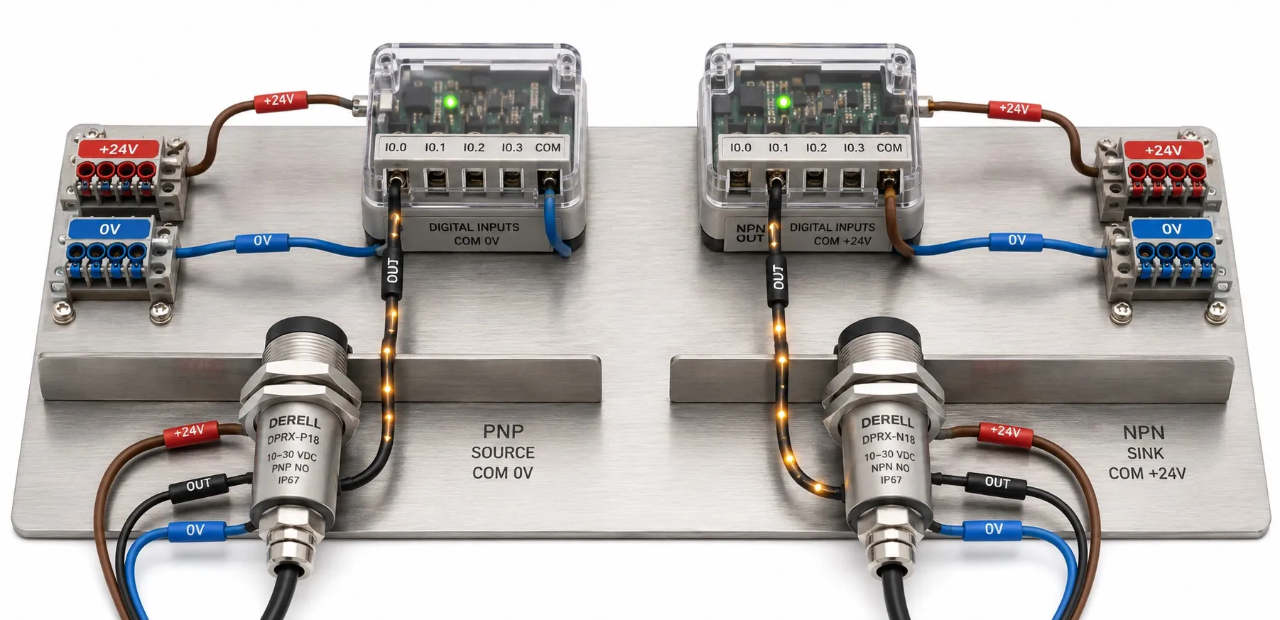
NPN or PNP? Sensor outputs and PLC wiring
Hello fellow automation professionals,
An active PNP output connects the load to the positive supply. An active NPN output connects the load’s return path to 0 V. In a 24 V DC system, remember: “PNP supplies positive; NPN pulls towards zero.” An NPN output does not generate −24 V.
PNP and NPN describe a sensor’s electrical output type, rather than its sensing principle. An inductive sensor, capacitive sensor or photoelectric sensor family may offer several output options. Choose the output to match the signal expected by the PLC input.
1. What do NPN and PNP mean in a transistor?
NPN and PNP are two different semiconductor structures used in bipolar junction transistors. Their terminals are the base (B), collector (C) and emitter (E). In normal conduction, an NPN base is biased more positively than its emitter; a PNP base is biased more negatively. Base current controls current through the collector–emitter path. Anode and cathode are not BJT terminal names.
An industrial sensor handles this control internally; the installer does not connect to its base terminal. External connections normally comprise supply positive, supply 0 V and a switching output. Here, 0 V is the DC supply reference. It is a different concept from AC neutral or protective earth (PE).
2. Animation: Same detection, different current paths
This demonstration compares 24 V DC, three-wire, normally open sensors connected to suitable PLC inputs. Automatic mode alternates between target present and absent. Select either condition to inspect it. Moving dots follow the circuit to show conventional current direction. Both inputs register DI = 1; the difference is which side of the load is switched.
PNP current path: +24 V → sensor output → PLC input load → 0 V. NPN current path: +24 V → PLC input load → sensor output → 0 V. This is a simplified model; the electronic output is represented by a functional switch symbol, rather than a mechanical contact. Voltages are idealised; sensor supply current, leakage and ON-state voltage drop are omitted. With reduced motion enabled, automatic mode stays in the detected state; the selection controls still work.
3. PNP and NPN compared
| Feature | PNP output | NPN output |
|---|---|---|
| Action when ON | Connects the load to positive supply. | Connects the load to 0 V. |
| Output behaviour | Sourcing: Supplies current to the load. | Sinking: Carries load current towards 0 V. |
| Load connection | Between OUT and 0 V. | Between +24 V and OUT. |
| Typical PLC input common | COM = 0 V | COM = +24 V |
| Compatible input circuit | A current-receiving sinking input. | A current-supplying sourcing input. |
| ON-state OUT voltage relative to 0 V | Close to the supply voltage. | Close to 0 V. |
| OFF-state output | Usually high impedance in an open-collector output. | Usually high impedance in an open-collector output. |
These common-terminal connections apply to typical input circuits. Some PLC input modules accept either output type; others have fixed common connections for each input group. A manufacturer may use “PNP input” to mean an input compatible with a PNP sensor. Check the wiring diagram before relying on sinking/sourcing terminology.
4. Three-wire sensor colours and connections
| Common colour | Function | 24 V DC example |
|---|---|---|
| Brown (BN) | Positive supply | +24 V |
| Blue (BU) | Supply reference | 0 V |
| Black (BK) | Switching output | PLC digital input terminal |
| White (WH), if present | Second output or a model-specific function | Follow the product diagram |
These colours are common conventions; the product label and datasheet take precedence. For PNP, connect black to the input and the suitable input group’s COM to 0 V. For NPN, connect black to the input and the suitable group’s COM to +24 V. Swapping brown and blue does not convert NPN into PNP. Isolate the supply before wiring and check the other inputs sharing that common terminal.
5. NO and NC are independent of PNP and NPN
NO and NC describe which detection condition activates the output. PNP and NPN describe the current path. The following table applies to a proximity sensor during normal operation:
| Sensor type | Target absent | Target detected |
|---|---|---|
| PNP NO | Output OFF. | OUT connects to positive supply. |
| PNP NC | OUT connects to positive supply. | Output turns OFF. |
| NPN NO | Output OFF. | OUT connects to 0 V. |
| NPN NC | OUT connects to 0 V. | Output turns OFF. |
An OFF output means an electronic output that is not conducting. Photoelectric sensors may use light-on/dark-on terminology, so also consider how the target affects the light path. NC operation can help reveal certain broken-wire conditions, but it does not make an ordinary sensor a safety sensor.
6. Checking output behaviour with a multimeter
Set the multimeter to DC voltage. Connect the black probe to 0 V and first check the supply at the brown wire with the red probe. Then move the red probe to the black output wire and compare readings with the target present and absent. DC voltage measurements are more meaningful with a compatible PLC input or the manufacturer’s recommended test load connected.
With a suitable input load, PNP NO normally measures near supply voltage when detecting and near 0 V when not detecting. With a suitable load connected to positive supply, NPN NO normally measures near 0 V when detecting and near supply voltage when not detecting. NC reverses the detection sequence. A voltage reading from an unloaded, floating output is insufficient to identify the output type reliably.
OFF-state leakage current and a meter’s high input impedance can produce intermediate readings. An arbitrary low-value resistor may overload the output. If a test load is required, use Ohm’s law to calculate current and power while staying within the sensor’s ratings. Never connect a meter in current mode across OUT and 0 V.
7. The sensor indicator is lit, but the PLC input does not change
Check output compatibility, the COM connection, supply voltage and whether the black wire reaches the intended input terminal. A sensor indicator may show detection, power or output status, depending on the model. Successful detection does not activate the PLC input unless the correct current path is complete.
If the voltage looks correct but the input is unstable, check the input threshold, OFF-state leakage current, input filter and switching frequency. A short detection pulse can be missed by the input filter or PLC scan. Many digital inputs use an optocoupler that needs sufficient input current; the presence of voltage alone is not enough.
8. Output conversion and other sensor interfaces
To connect an NPN sensor to a PNP-compatible input, use a suitable NPN-to-PNP converter, isolated interface or correctly rated interposing relay. The relay coil must stay within the sensor’s voltage and current ratings. A DC coil may require manufacturer-approved suppression, such as a reverse-connected flyback diode across the coil. Suppression can increase release time.
A push-pull output can actively drive both voltage levels. Complementary outputs may provide separate NO and NC signals; these are different features. Two-wire sensors, NAMUR sensors, 4–20 mA and 0–10 V analogue outputs are not wired like the three-wire switching example above.
9. Which output should I choose?
For an existing machine, match the input card’s requirements and all relevant specifications of the original sensor. For a new design, select the PLC, sensors and interfaces together. PNP may be common in a particular system, but that does not inherently make it more accurate, faster or higher quality.
Alongside electrical compatibility, consider the target material, sensing distance, mounting arrangement, ambient temperature and IP protection rating. Our comparison of sensing technologies can help with that choice. Choose the right sensing principle, then match the output to the input.