
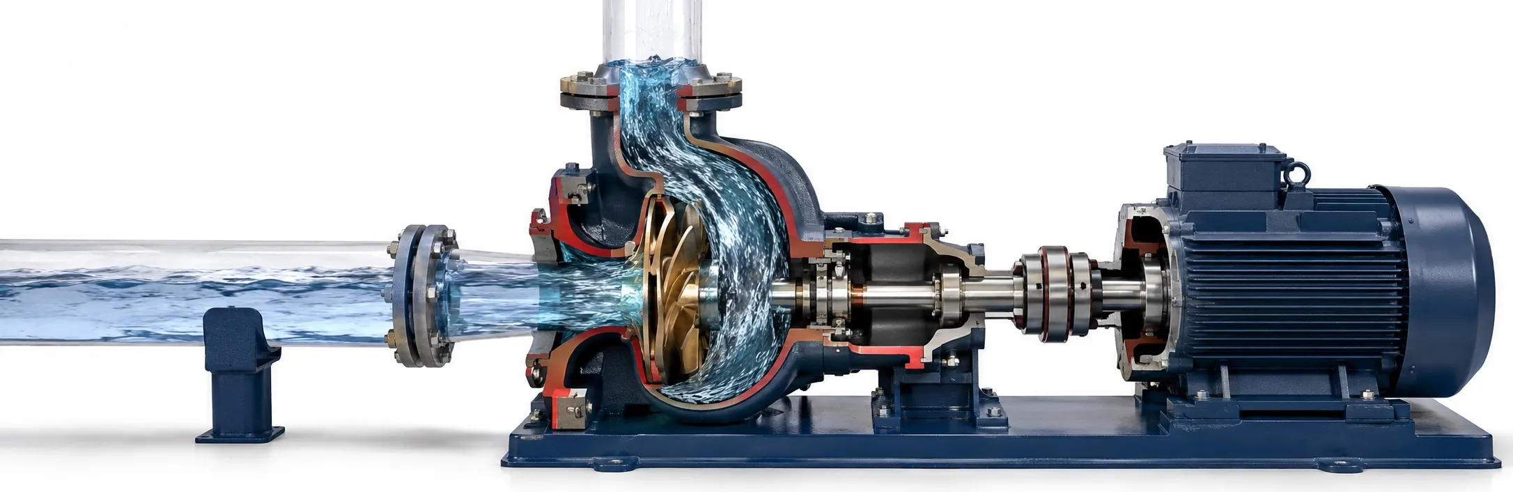
How a pump turns shaft motion into fluid movement
A pump transfers mechanical energy to a fluid. That added energy can move liquid through pipework, raise it to another level or keep it circulating. In a typical motor-driven pumping system, the motor supplies rotation, but an impeller, piston, diaphragm or gear set must pass that motion to the liquid. The pump's components also support the moving parts and maintain the necessary seals.
The job comes first: transfer, circulation and pressure boosting may call for different designs. Two important mechanisms explain much of the difference between pump types: adding energy through a rotating impeller and moving liquid in enclosed working volumes.
Follow the liquid through a centrifugal pump
In a typical radial-flow centrifugal pump, liquid enters near the impeller's centre. Rotating blades transfer energy to it and direct the flow towards the outer edge. Pressure rises within the impeller too. The volute or diffuser collects the flow and converts some of its velocity energy into additional pressure. It is misleading to assign all pressure generation to the casing.
As fresh liquid reaches the inlet, flow continues. Its rate depends on the connected installation: the actual operating point lies where the pump's head–flow curve intersects the system curve. Pipework resistance, valve position and elevation all matter. That is why selecting a pump starts with the required flow and total head, rather than motor kilowatts alone.
A piston pump moves a changing volume
A positive displacement pump handles liquid in working volumes. In a simple piston arrangement, withdrawing the piston enlarges the chamber and opens the inlet check valve. The return stroke reduces the volume, closes the inlet and opens the discharge valve. The check valves make the two strokes produce one-way delivery.
A diaphragm pump changes chamber volume with a flexible membrane. A gear pump carries liquid around the casing in spaces between the teeth and the casing wall. For a fixed-displacement design, speed and volume per cycle determine theoretical flow; internal leakage can reduce actual delivery. When comparing water and oil pumps, viscosity and seal or material compatibility therefore deserve attention.
Blocking a positive displacement pump's discharge can cause dangerous overpressure. The installation needs suitable pressure-limiting protection. A centrifugal pump also has limits on operation with a closed discharge: follow its minimum-flow and operating requirements. Overheating is a reason to investigate the duty, not a normal consequence to accept.
Why a spinning motor may deliver no water
A pressure difference at the inlet allows liquid to move towards the pump. When drawing from an open tank, atmospheric pressure helps push liquid into the suction line. Consequently, suction lift is limited; liquid temperature, altitude and inlet losses affect the available suction conditions. A submersible pump changes the installation arrangement by operating within the liquid, but still has defined operating limits.
A non-self-priming centrifugal pump needs the specified initial filling and air removal before starting. Air in the casing, an inlet air leak or inadequate liquid supply can leave the motor turning without useful delivery. These belong in a pump-fault investigation before concluding that the motor needs replacing. Self-priming models also have instructions for their initial liquid fill.
Separate flow, head and power
Flow rate tells you how much liquid moves per unit time. Head expresses the energy added per unit weight of liquid. Power measures the rate of that energy transfer. The basic hydraulic power calculation is Phydraulic = ρ × g × Q × H. With Q in m³/s and H in metres, the result is in watts.
For water, a duty of 3.6 m³/h at 20 m total head represents approximately 196 W of hydraulic power. Assuming 60% pump efficiency gives about 327 W at the shaft; electrical input is higher because the motor has losses. This example explains the energy balance rather than specifying a motor. Pump efficiency influences the cost of ownership, alongside the rest of the installation.
Changing speed changes the available performance
Adjusting centrifugal-pump speed shifts its characteristic curve; the system then determines the new flow. A pump controller using PID control can compare measured pressure with a target and adjust speed in a suitable installation. With several pumps, pump alternation manages operating order and runtime distribution. Minimum flow, cooling and permitted speed range still apply. Reducing energy consumption means matching the duty within those limits.