
Gd10 fault codes
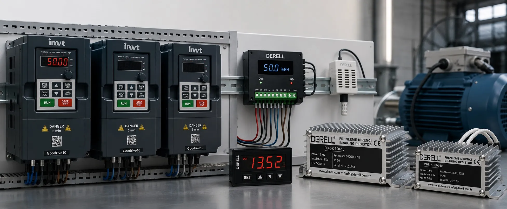
INVT GD10 Fault Codes and Diagnostic Records
When an INVT Goodrive10 (GD10) trips, the code shown on the keypad is only the first part of the diagnosis. The GD10 also stores operating information from the moment of the fault, allowing the technician to review motor frequency, output current, DC-bus voltage, temperature and terminal status.
The P07 parameter group is therefore particularly useful for intermittent faults that disappear after a reset. Overcurrent, overvoltage, undervoltage, overload, overtemperature and communication faults should be evaluated together with these stored operating values.
Fault Indication and Reset
When the TRIP indication is active, the keypad displays the fault detected by the drive. Before resetting the GD10, record the displayed code and check the stored P07 information where possible.
After the actual cause has been corrected, the drive can be reset:
- With the STOP/RST key
- Through a digital input assigned to fault reset
- By cycling the drive power where appropriate
Do not repeatedly reset and restart the motor without finding the cause of the trip. A recurring fault may indicate a motor, load, wiring, supply-voltage or drive-parameter problem.
Recommended GD10 Troubleshooting Sequence
1. Check the keypad and operator-panel connection.
2. Read the displayed GD10 fault code.
3. Review the P07 fault history.
4. Check the operating data stored at the time of the fault.
5. Inspect the motor, power wiring, supply voltage and mechanical load.
6. Correct the actual cause before resetting and restarting the drive.
P07.27 - P07.32 Fault History
P07.27: Current fault type
P07.28: Last fault type
P07.29: Second previous fault type
P07.30: Third previous fault type
P07.31: Fourth previous fault type
P07.32: Fifth previous fault type
GD10 Fault Code Numbers
0: No fault
4 - OC1: Overcurrent during acceleration
5 - OC2: Overcurrent during deceleration
6 - OC3: Overcurrent at constant speed
7 - OV1: Overvoltage during acceleration
8 - OV2: Overvoltage during deceleration
9 - OV3: Overvoltage at constant speed
10 - UV: DC-bus undervoltage
11 - OL1: Motor overload
12 - OL2: VFD overload
15 - OH1: Rectifier module overtemperature
16 - OH2: Inverter module overtemperature
17 - EF: External fault
18 - CE: RS485 communication fault
21 - EEP: EEPROM operation fault
22 - PIDE: PID feedback offline fault
24 - END: Configured operating-time limit reached
25 - OL3: Electronic overload
36 - LL: Electronic underload fault
Note: GD10 fault numbers are not continuous. Missing numbers in this list should not be filled with fault definitions from other INVT drive families.
P07.33 - P07.40 Current-Fault Snapshot
P07.33: Operating frequency at the time of the fault
P07.34: Ramp reference frequency
P07.35: Output voltage
P07.36: Output current
P07.37: DC-bus voltage
P07.38: Maximum recorded temperature
P07.39: Digital input-terminal status
P07.40: Output-terminal status
These values provide a snapshot of what the GD10 was doing when the fault occurred. For example, P07.36 is useful when investigating an OC trip, while P07.37 is particularly relevant to OV and UV faults.
P07.41 - P07.48 Previous-Fault Snapshot
P07.41: Operating frequency
P07.42: Ramp reference frequency
P07.43: Output voltage
P07.44: Output current
P07.45: DC-bus voltage
P07.46: Maximum temperature
P07.47: Digital input-terminal status
P07.48: Output-terminal status
P07.49 - P07.56 Earlier-Fault Snapshot
P07.49: Operating frequency
P07.50: Ramp reference frequency
P07.51: Output voltage
P07.52: Output current
P07.53: DC-bus voltage
P07.54: Maximum temperature
P07.55: Digital input-terminal status
P07.56: Output-terminal status
How to Use the Stored Fault Data
A fault code should be compared with the machine condition at the time of the trip. For example:
- For OC1 / OC2 / OC3, check the recorded output current and mechanical load.
- For OV1 / OV2 / OV3, review DC-bus voltage and braking conditions.
- For UV, compare the DC-bus value with the incoming supply condition.
- For OH1 / OH2, review temperature, cooling and motor load.
- For EF, check the stored digital-input status and the external device connected to the fault input.
Important: Values such as 0.00 Hz, 0 V or 0.0 A shown in parameter documentation are default display values. During a real fault, the P07 records contain the operating values captured by the drive.
Safety: Electrical inspection and maintenance of the GD10 should only be performed by qualified personnel. Isolate the power supply and follow the drive safety instructions before working on the VFD, motor or associated wiring.
GD10 Detailed Fault Troubleshooting
+ INVT GD10 Fault Codes - Page 2
Related INVT GD10 Resources
+ INVT GD10 User Manual (English PDF)
+ INVT General Fault Codes and Troubleshooting
+ INVT Commissioning and Application Notes