
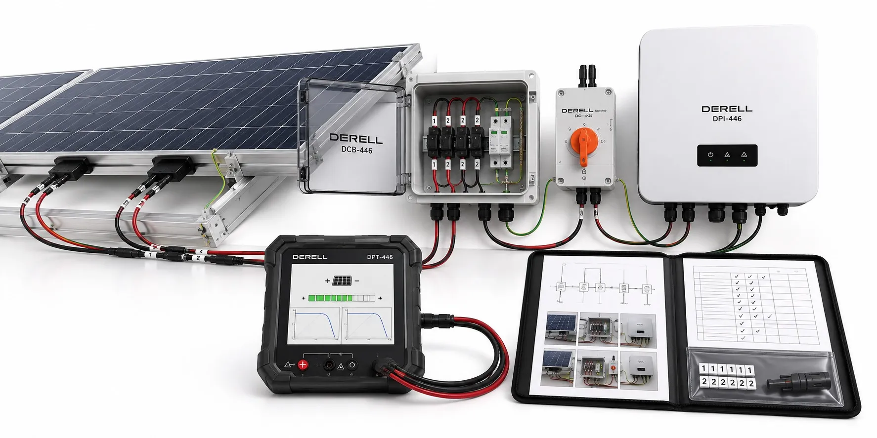
IEC 62446: What a Proper PV Handover Should Demonstrate
IEC 62446 is a family of standards covering testing, documentation and maintenance for photovoltaic systems. At commissioning, seeing the inverter produce power is only one observation. The owner also needs evidence of what was inspected, which circuits were tested and how the results were assessed.
An operating solar array can still contain wiring, insulation or protection defects. A useful handover package turns “the system works” into a traceable engineering record.
The Three Documents Serve Different Purposes
IEC 62446-1 addresses documentation, commissioning tests and inspection for grid-connected PV systems. The consolidated edition checked in the IEC catalog on October 1, 2026 is IEC 62446-1:2016+AMD1:2018. Part 1 replaced the earlier IEC 62446:2009 publication.
IEC 62446-2:2020 covers preventive, corrective and performance-related maintenance of grid-connected systems. It provides a framework for activities such as module maintenance, connection checks, troubleshooting and safe working practices.
IEC TS 62446-3:2017 deals with outdoor infrared inspection of operating PV modules and plants. This technical specification addresses equipment, inspection conditions, reporting and personnel competence.
Build a Handover File That Matches the Site
Identify the installation: Record the location, installed capacity, commissioning date, responsible organizations and equipment details. Later alterations should remain traceable rather than disappearing into an outdated drawing set.
Provide as-built drawings: Single-line diagrams, string layouts, cable routes and protective-device information should describe the actual installation. The series and parallel configuration must be clear, including which strings feed each inverter and MPPT input.
Include operating information: Supply equipment data, installation manuals, warranties, shutdown instructions and maintenance guidance. Evidence relating to module safety and power converter safety supports the file, but does not replace inspection of the installed equipment.
Inspect Before Relying on Measurements
Visual inspection can reveal damaged cables, unsuitable connector combinations, poor cable support, missing identification and problems with switches or protective devices. Module glass, frames, junction boxes and mounting points also need attention.
Compare the protective earthing and bonding arrangement with the design. A conductor that appears connected has not necessarily had its continuity verified. Equally, a tidy connector housing does not prove that its internal termination is sound.
What Do Commissioning Tests Establish?
Protective conductor continuity: Verify the required protective and bonding connections using an appropriate method. This is a different measurement from the resistance of an earth electrode.
Polarity and open-circuit voltage: Check DC polarity and compare string voltage with the module count, temperature and equipment data. A plausible Voc reading does not establish that the string delivers its expected power under load.
String current: Depending on the applicable test plan, current verification can use short-circuit or operating-current measurements. Results need to be interpreted against irradiance, temperature and string configuration. The solar inverter’s operating state or power limitation can also affect operating-current readings.
Insulation resistance: Assess insulation using the appropriate test voltage, method and acceptance criteria. Establish how the inverter, surge protection, optimizers and other electronics must be isolated or protected before testing. One test voltage cannot be applied indiscriminately to every installation.
Functional checks: Verify applicable switching, control and protective functions. Combiner-box checks and other examinations may also be required. The test sequence and scope must reflect the installation and the standard edition being applied.
Category 1 and Category 2 Testing
Category 1 is the basic commissioning test regime. Category 2 provides further assessment, where applicable, through methods such as I–V curve measurement and infrared inspection. Advanced diagnostics do not justify skipping the basic electrical checks.
An I–V curve describes the string’s current-voltage behaviour across operating points. Infrared inspection looks for unusual thermal patterns. These methods reveal different aspects of condition; neither is a direct substitute for insulation testing.
Choose Instruments for the Actual Circuit
A general-purpose multimeter should not be assumed to cover every PV test. Check DC voltage limits, current capability, suitability for the application and the relevant measurement category.
The test leads and probes need suitable ratings too. If a current clamp is used for operating-current measurements, confirm that it measures DC. Include instrument identification and calibration status in the records.
A PV short-circuit test is not an invitation to place an ordinary multimeter’s current input across a string. It requires properly rated equipment, a suitable procedure and competent personnel. Illuminated modules continue generating voltage even when the inverter has stopped.
Interpret the Reading Before Naming the Fault
Example: Three strings with the same module type and count produce operating-current readings of 12.0 A, 12.2 A and 8.1 A. The third string deserves investigation, but the reading alone does not prove module failure. Possible explanations include shading, soiling, a connection problem, a different MPPT operating point or changing irradiance during measurement.
Sequential measurements are especially vulnerable to changing weather conditions. These example readings are not a pass/fail threshold from the standard. They illustrate why a useful measurement record includes the conditions under which the values were obtained.
Thermal Inspection Is Not an Energy-Yield Assessment
A hot area may indicate a cell, diode or connection problem. Reflections, wind, irradiance and electrical loading also influence thermal images. A thermography report should identify the component, record the inspection conditions and explain the significance of the finding. A coloured image without that context is weak diagnostic evidence.
Module efficiency, instantaneous plant output and performance ratio describe different things. IEC 61724-1 is the relevant reference for PV performance monitoring and analysis. Passing commissioning tests under IEC 62446 does not guarantee a particular annual energy yield.
Make Every Result Traceable
A useful report links each result to a string or circuit, the test method, relevant conditions, the instrument used and the assessment. Record defects, corrective work and repeat-test results. A sheet containing only “pass” boxes offers little help when the same circuit develops a problem later.
Commissioning records provide a baseline for future inverter maintenance and investigations into falling production. Inspection intervals should reflect site conditions, manufacturer guidance, fault history and applicable requirements. The records should remain usable throughout the life of the installation.