
IEC 61851
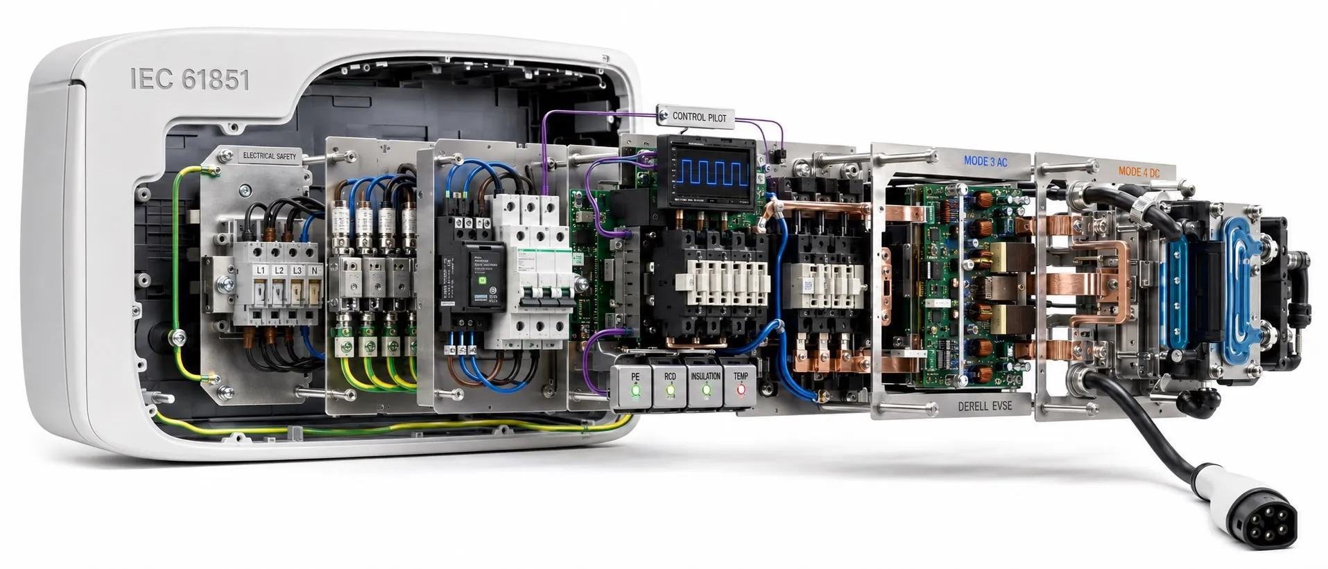
A framework for safe, controlled and compatible conductive charging
IEC 61851 is a series of standards addressing conductive charging, where energy reaches an electric vehicle through cables and electrical contacts. Within electric vehicle charging systems, it covers more than the shape of a plug: equipment operating conditions, the vehicle connection, control functions and electrical safety are also involved. When assessing charging standards, identify the relevant part, edition and application conditions rather than relying on the series number alone.
Editor's note: Charging mode, connector type and power rating describe different properties. “Mode 3”, “Type 2” and “22 kW” are not three names for the same feature. The main IEC family for wireless charging is IEC 61980; IEC 61851-25 is not a wireless charging part. A claim of IEC 61851 compliance alone does not establish compatibility with every vehicle or communication option.
What do the main parts cover?
IEC 61851-1:2017: Covers general requirements, charging modes and the control framework. The text available through the IEC catalogue incorporates the 2023 corrigendum. IEC 61851-22:2001 has been withdrawn, and its former AC charging station requirements were transferred to Part 1. It should therefore not be presented as a current, standalone AC charging station standard.
IEC 61851-21-1:2017: Addresses electromagnetic compatibility of the vehicle's onboard charging system while connected to the supply. IEC 61851-21-2:2018 addresses EMC requirements for off-board charging equipment. Together, they replaced IEC 61851-21:2001. The onboard converter and the external charging station should not be assigned to the same EMC test scope without checking the applicable requirements.
IEC 61851-23:2023: Addresses DC electric vehicle supply equipment, including safety and energy transfer requirements. IEC 61851-24:2023 concerns digital communication between the vehicle and equipment to control DC energy transfer. Power equipment requirements and communication requirements are therefore distinct but coordinated layers.
IEC 61851-25:2020: Covers particular DC supply equipment with outputs not exceeding 120 V DC and 100 A DC, where protection relies on electrical separation. IEC TS 61851-3-1:2023 is a technical specification for equipment with outputs up to 120 V DC where protection against electric shock relies on double or reinforced insulation. Their protective approaches differ; “Part 3 covers all DC charging” is not an accurate description.
IEC 61851-23-1:2026 addresses certain DC charging systems using an automated connection device. IEC 61851-23-3:2026 addresses megawatt charging systems (MCS). High-power charging involves more than thicker cables: connections, thermal management, power electronics and communication must work together. These are examples of specialised applications alongside the commonly used core parts.
Mode 1, Mode 2, Mode 3 and Mode 4
Mode 1: AC charging through a standard socket without a dedicated control pilot between the vehicle and charging point. Its use depends on local rules; an ordinary socket should not be assumed suitable for sustained vehicle charging.
Mode 2: AC charging using an in-cable control and protection device (IC-CPD). IEC 62752 is also relevant to that device. Portable equipment for charging a vehicle at home may use this arrangement, but the control box does not correct every deficiency in the installation.
Mode 3: AC charging through dedicated equipment with a vehicle control function. Fixed wallboxes and many AC charging points use this arrangement.
Mode 4: Off-board equipment supplies DC, with energy transfer coordinated between the equipment and vehicle. The difference between AC and DC charging includes where power conversion takes place, not just charging speed.
Control pilot, cable information and actual charging power
CP (Control Pilot) is a control interface used to assess connection and charging states. In basic AC charging, its PWM signal can communicate the available current. In Type 2 arrangements, the PP (Proximity Pilot) circuit provides functions such as coding the cable's current capacity. CP and PP do not constitute the complete high-level digital communication system. Closing the power contactor before the necessary conditions have been verified does not provide a safe charging sequence.
For example, a 22 kW AC station cannot make a vehicle with an 11 kW onboard charger draw 22 kW. The applicable limits of the supply, cable, vehicle and current control settings govern the result. During DC charging, battery state of charge, temperature and vehicle demand also change the power level. The distinction between kW and kWh matters: one measures power, while the other measures transferred energy.
How connector and communication standards fit together
IEC 62196 concerns connection accessories such as plugs, socket-outlets, vehicle connectors and inlets. ISO 15118 is the family for high-level communication between the vehicle and supply equipment. A connector fitting physically does not establish compatibility of the software and charging profiles. Interfaces encountered within CCS, CHAdeMO and SAE J1772 applications must be assessed against the intended market and vehicle support.
Wireless power transfer is addressed by the IEC 61980 series. Removing the cable and conductive contacts does not remove the safety requirements: alignment, communication, efficiency and EMC require their own assessment.
Assess electrical protection and the installation together
Protective earthing, overcurrent protection and residual current protection serve different purposes. AC charging points must also account for the effects of DC residual current on protective devices. Depending on the application, arrangements include a Type B RCD or a suitable Type A RCD combined with 6 mA DC detection and disconnection. Built-in DC detection does not automatically eliminate all external protection requirements; the equipment instructions and installation rules remain essential.
Fixed installations must also take account of relevant requirements such as IEC 60364-7-722. Assess cable current-carrying capacity, voltage drop, distribution board capacity, surge protection and environmental conditions together. For outdoor equipment, the IP protection rating also matters. Charging through an extension lead cannot be considered suitable simply because the plugs fit.
Bidirectional charging and solar integration
V2G involves energy transfer to the grid, while V2H involves supplying a home; neither is a feature of every charger. ISO 15118-20 includes communication functions for bidirectional transfer, while the bidirectional scope of IEC 61851-23:2023 is limited according to the system involved. Communication support does not replace suitable power hardware or grid connection requirements. Solar-powered vehicle charging can also use unidirectional load management: charging from solar power does not establish V2G capability.
Which information should you request when choosing equipment?
Look beyond a single standards logo. Check the applicable part and edition, AC/DC operating range, mode, connector, protection arrangement, installation conditions and the scope of relevant test reports. A compliant component does not establish compliance of the complete charging station. A project must consider total demand, load management, vehicle compatibility and commissioning verification together. The electric vehicle charging FAQ provides related application topics.
This overview is based on publication records reviewed on 17 October 2026. Specifications and conformity assessments must also check the applicable edition, amendments and requirements in the intended country.
Related topics
Within the charging family, explore IEC 62196 connection accessories, ISO 15118 communication, CCS connectors, CHAdeMO and the electric vehicle charging FAQ.
Related categories include residual current protective devices, earthing, contactors, cable current-carrying capacity and IP protection ratings, covering different parts of the installation.
Electric vehicles and charging systems, charging standards and AC/DC charging comparison.
Technical sources
IEC 61851-1:2017 and the 2023 corrigendum; IEC 61851-22: withdrawal record; IEC 61851-21-1:2017; IEC 61851-21-2:2018
IEC 61851-23:2023; IEC 61851-24:2023; IEC 61851-25:2020
IEC TS 61851-3-1:2023; IEC 61851-23-1:2026; IEC 61851-23-3:2026
IEC 61980-1:2020: wireless charging; IEC 62196-1:2025: connection accessories
ISO 15118-20:2022: high-level and bidirectional communication
Phoenix Contact: principles of AC/DC charging and charging modes
CIRCUTOR: residual current protection for electric vehicle charging