
IEC 60751 Pt100/Pt1000 Tolerance Classes
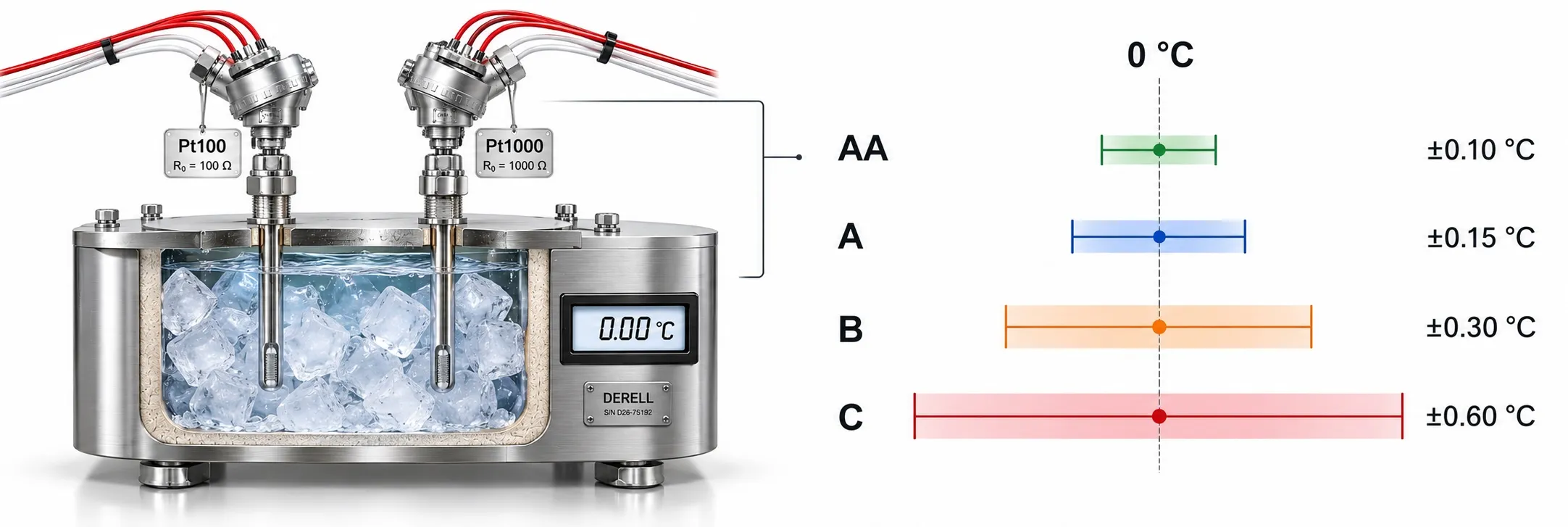
IEC 60751 Pt100/Pt1000 Tolerance Classes
A tolerance class specifies how far a platinum resistance thermometer may deviate from the standard resistance–temperature curve at a given temperature. IEC 60751 covers industrial platinum thermometers and measuring elements. For classes AA, A, B and C, the allowed deviation depends on temperature; “Class A measures within ±0.15 °C at every temperature” is incorrect.
How do Pt100 and Pt1000 differ?
A Pt100 has a nominal resistance of 100 Ω at 0 °C; a Pt1000 has 1000 Ω. On the same nominal curve, Pt1000 resistance is ten times Pt100 resistance. However, at the same valid temperature and class, their tolerance in °C is identical. Higher resistance alone does not mean a tighter temperature tolerance.
On the standard nominal curve, 100 °C corresponds to approximately 138.51 Ω and 1385.06 Ω, respectively. Detailed conversion uses the Callendar–Van Dusen equation. Pt1000 is less sensitive to the temperature error caused by a given lead resistance; this advantage does not change its tolerance class.
Calculating AA, A, B and C tolerances
The values below apply to thermometer classes. t is temperature in °C; |t| means its absolute value. The formulas return °C and apply only within the declared validity range.
| Class | Tolerance (°C) | At 0 °C (°C) | At 100 °C (°C) |
|---|---|---|---|
| AA | ±(0.10 + 0.0017 × |t|) | ±0.10 | ±0.27 |
| A | ±(0.15 + 0.002 × |t|) | ±0.15 | ±0.35 |
| B | ±(0.30 + 0.005 × |t|) | ±0.30 | ±0.80 |
| C | ±(0.60 + 0.010 × |t|) | ±0.60 | ±1.60 |
For example, Class A tolerance at 100 °C is ±0.35 °C. Considering only the thermometer's deviation from the nominal curve, the limits correspond to 99.65–100.35 °C. This does not guarantee the same error limit for the connected display or the complete measuring system.
Use the absolute value for negative temperatures too: for Class A at −20 °C, ±(0.15 + 0.002 × 20) = ±0.19 °C. A negative temperature does not reduce the tolerance.
Temperature ranges of class validity
The standard class ranges differ for thermometers built with wire wound and thin film elements. This table applies to complete thermometers; the product's sheath, cable and connections may further restrict its operating range.
| Class | Thermometer with wire wound element | Thermometer with thin film element |
|---|---|---|
| AA | −50 … +250 °C | 0 … +150 °C |
| A | −100 … +450 °C | −30 … +300 °C |
| B | −196 … +600 °C | −50 … +500 °C |
| C | −196 … +600 °C | −50 … +600 °C |
For example, the standard AA range for a thin film thermometer is 0…150 °C. This table does not establish AA performance at 200 °C. Being able to operate and maintaining class tolerance are different requirements. A special range requires an explicit manufacturer declaration.
Is the element class the same as the probe class?
Bare platinum measuring elements use designations such as F 0.1 / F 0.15 / F 0.3 / F 0.6 and W 0.1 / W 0.15 / W 0.3 / W 0.6. F denotes thin film; W denotes wire wound construction. Do not confuse the element's tolerance and validity range with the assembled thermometer's declaration.
For descriptions such as “1/3 DIN” or “1/10 DIN”, establish which base tolerance is being reduced and over which temperature range. 1/3 Class B is not automatically identical to Class AA. IEC 60751:2022 provides separate declarations and -sp marking for special tolerances and ranges.
How do wiring and electronics affect the result?
2-, 3- and 4-wire connections affect measurement. In a 2-wire circuit, lead resistance adds to the reading. With 3 wires, compensation accuracy depends on matching lead resistances; a 4-wire measurement largely removes this effect. Thermometer classes tighter than B require 3 or 4 wires.
Calculated example: near 0 °C, a total additional series resistance of 1 Ω in a 2-wire circuit causes approximately +2.6 °C error for Pt100 and +0.26 °C for Pt1000. These estimates use the local slope of the nominal curve; cable material and temperature affect the actual result.
Also assess self-heating and lead resistance errors, insufficient immersion and thermal contact, electronic input error and drift. Adding a temperature transmitter or temperature controller introduces its specifications too. Measurement accuracy cannot be determined from the sensor label alone; a display step of 0.1 °C does not mean ±0.1 °C accuracy.
Selection and verification
When selecting a Pt100 sensor, specify the temperature range, wire configuration and insertion length alongside the class. A head mounted Pt100 or custom Pt100 design alone does not identify its accuracy class. Calibration reports deviation and measurement uncertainty at selected points; a good result at one point does not establish class conformity across the entire range.
These classes cannot be transferred directly to thermocouple, NTC or PTC sensor products. For technology selection, consult the Pt100 versus thermocouple comparison alongside industrial temperature measurement standards.
Editor's note
Before asking which class is best, establish the operating range and allowable total measurement error for the process. Avoid losing a tight tolerance probe's benefit in a long 2-wire cable. Specify sensor type, class, valid temperature range and connection together when ordering.
Related topics
ASTM E1137/E1137M · RTD connection methods · Pt100 resistance–temperature conversion
External reference links
IEC — IEC 60751:2022 scope and edition
IEC 60751:2022 — preview of the standard
WIKA — thermometer and measuring element classes
WIKA IN 00.17 — platinum thermometers and tolerances
WIKA — 2-, 3- and 4-wire connections
WIKA — Pt100, Pt1000 and NTC comparison