
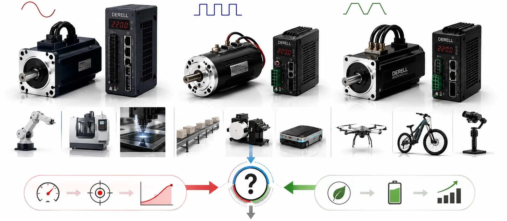
Choosing a servo motor starts with the job the axis must perform and the hardware it must work with. AC, DC and brushless are overlapping descriptions, not three mutually exclusive product classes. An industrial AC servo can also be brushless. Evaluate the motor as part of an axis: drive, feedback, transmission and load all influence the result.
Read the construction and control details behind the label
| Catalog description | What to check |
|---|---|
| Brushed DC servo | Brushes and a commutator switch current between windings. Check compatibility with the existing machine and access for brush maintenance. |
| AC servo / PMSM | A common industrial AC servo design is a permanent-magnet synchronous motor. It is brushless and needs a compatible drive and rotor-position information. |
| BLDC / EC servo | Commutation is electronic. The supported motor/drive combination may use block commutation, sinusoidal commutation or FOC. The BLDC label does not specify low-speed smoothness. |
A DC-powered system does not necessarily use a brushed motor. A brushless drive can take energy from a DC bus and generate controlled phase currents. Block commutation may introduce torque ripple that matters at low speed. Smooth operation depends on the motor, sensing and supported control method together.
Size the duty cycle, not just the nameplate power
Use the load and transmission calculation to establish friction, gravity loads, inertia and acceleration demand. Check continuous torque, peak torque, peak duration and operating speed. A winding application using torque control has different requirements from a fast positioning axis. Read the torque-speed capability for the actual motor/drive pairing and supply voltage.
For demanding cycles, dynamic response depends on more than maximum rpm. A gearbox may improve the motor-side load relationship, but introduces losses, backlash and a different motor-speed requirement. There is no universal ideal load-to-motor inertia ratio.
A short torque pulse can change the thermal requirement
Worked example: an axis repeats a four-second cycle with 4 Nm for one second and 1 Nm for three seconds. A simplified RMS calculation gives Trms = √[(4² × 1 + 1² × 3) ÷ 4] ≈ 2.18 Nm. The arithmetic average, 1.75 Nm, does not represent the same heating assessment.
A motor with only 2 Nm of available continuous torque under these conditions fails this preliminary check. Separately verify that the motor and drive can produce 4 Nm at the required speed for the full one-second interval. RMS sizing is a starting point: confirm thermal behavior, cooling, mounting conditions, speed and the manufacturer's overload limits.
Match feedback and drive before comparing performance
For an encoder or resolver, check its electrical interface, protocol and rotor-position requirements as well as resolution. An absolute encoder can provide position information without every design requiring a battery. Encoder resolution, axis accuracy and repeatability are different specifications. The mechanics still affect accuracy and position repeatability.
A supported motor-and-drive combination must account for winding data, voltage, current, temperature sensing, cables and configuration. The drive also needs the command interface used by the controller, such as pulse and direction or EtherCAT. A matching connector and equal power rating do not establish compatibility. Include any multi-axis synchronization requirements before selecting the system.
Check the installation, environment and holding requirements
AC does not automatically mean a higher permitted ambient temperature. Use the model's operating limits and derating data for temperature and altitude. Check the IP rating, including relevant IP65/IP66 or IP67 options, alongside shaft sealing, connector protection and cleaning conditions. Removing brushes does not make a motor dustproof or waterproof.
Confirm flange and shaft dimensions, permitted radial and axial loads, cable clearance and available space. Select a holding brake when the load needs holding; it is not the normal mechanism for stopping every production move. Compare size, weight and energy efficiency at the application's actual duty cycle.
Compare the complete cost and prepare a useful specification
Brushless construction removes brush and commutator servicing, but bearings, seals, cables, brakes and feedback still need attention. Include maintenance, commissioning, spare parts and downtime when comparing motor and drive costs. The name alone cannot prove that a DC solution is cheaper or that a brushless model will last longer in a particular installation.
Prepare the load, travel, cycle time, acceleration, speed, supply, mounting dimensions, environment and feedback requirements. For a replacement, add the complete existing motor and drive model codes. After selection, correct configuration and commissioning are essential to achieve the expected performance.