
How does Ethernet work?
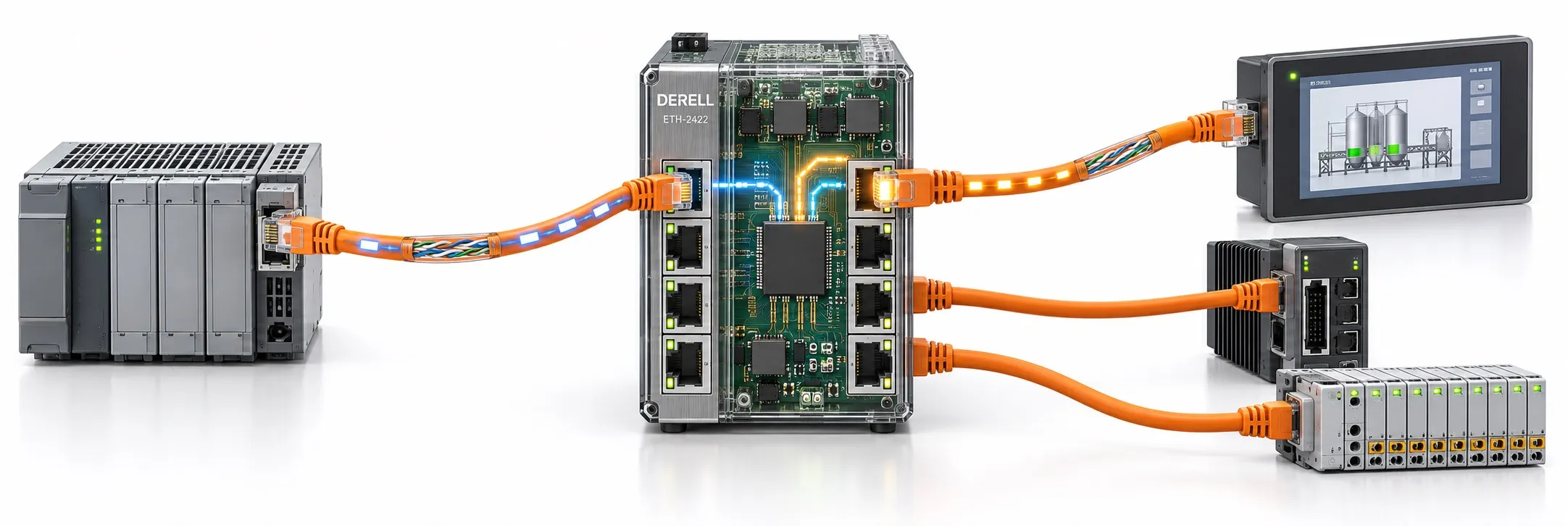
How does Ethernet work?
Trace the exchange · Errors and retransmission · Speed and timing · Troubleshooting
Ethernet moves data in frames addressed with MAC addresses. A network interface builds a frame, the physical layer turns it into signals, and a switch decides which local port should carry it onward. What the message actually means—“read this temperature,” for example—is defined by the application protocol, not by Ethernet. The Ethernet overview introduces the technology; the wider industrial communication section covers the other protocol families. [1] [7] [13]
Think of it this way: A machine’s display and controller exchange addressed envelopes. Ethernet provides the delivery arrangements, and the switch sorts envelopes toward the right exit. The software at each end must still understand what is written inside. Delivering a letter to the correct door does not make its contents meaningful to the recipient. Likewise, a working Ethernet link does not prove that two automation devices can exchange useful data.
The example below uses an ordinary switched, full-duplex Ethernet network. IEEE 802.3 covers the Ethernet MAC and physical layers; the IEEE 802.1Q family covers bridging and VLAN behavior. Treating a switch as just another physical-layer component, alongside a cable, misses this distinction. [1] [2]
Follow a temperature request from an HMI to a PLC
Our example has an HMI operator panel, a PLC, and one switch between them. Assume that both devices support Modbus TCP and have been configured for it. The HMI needs to read a temperature value from the PLC. All addresses and port assignments below are illustrative; they are not factory settings for any particular product.
HMI: 192.168.10.20/24, MAC 02:00:00:00:10:20, connected to switch port 2. PLC: 192.168.10.10/24, MAC 02:00:00:00:10:10, connected to switch port 5. Both ports belong to the same VLAN and allow forwarding. The /24 mask is 255.255.255.0. The MAC addresses are example values too.
1. Establish the physical links
There are two separate links: HMI to switch, and switch to PLC. Compatible copper ports can negotiate their supported speed and duplex settings. For this example, both links operate at 100 Mbit/s full duplex. The network interface, cable type and permitted link length matter here. A lit link indicator is not evidence that the IP configuration or PLC protocol is correct. [3]
2. Decide whether the destination is local
The HMI’s IP layer evaluates 192.168.10.10 against its own address and subnet mask. In this example the PLC is on the same subnet, so delivery is direct. For a destination on another subnet, the routing table selects a next hop—often the default gateway in a simple installation. This is an IP routing decision, not a job performed by the Ethernet switch’s ordinary Layer 2 forwarding process. [4]
3. Resolve the next-hop MAC address
When the PLC’s MAC address is not already in the HMI’s ARP cache, the HMI sends an ARP request asking which device owns 192.168.10.10. Its Ethernet destination is the broadcast address FF:FF:FF:FF:FF:FF. The PLC recognizes its IP address and normally returns a reply identifying its MAC address. The result can be cached: reading another temperature value does not require a fresh ARP exchange every time. [5]
Keep the two tables separate. The HMI’s ARP cache maps IP addresses to MAC addresses. The switch’s forwarding table associates MAC addresses with ports in the relevant VLAN context. These are different functions. On IPv6 networks, address resolution uses Neighbor Discovery rather than ARP. [5] [6] [8]
4. Let the switch learn from incoming frames
The switch associates the HMI’s source MAC address with port 2. When the PLC’s ARP reply arrives, it learns the PLC’s address through port 5. Forwarding decisions then use the destination MAC address. In this example, the ARP exchange helps both the endpoint’s address resolution and the switch’s learning process. This selective forwarding explains an important difference between a switch and a hub. [8] [9]
An ordinary learning switch does not always know the destination. For an unknown unicast address, it normally floods the frame through eligible forwarding ports in the same VLAN, except the ingress port. Broadcast traffic also stays within the VLAN’s forwarding scope. Port states and configured controls can restrict delivery. “A switch only sends to the intended device” therefore leaves out unknown destinations and broadcasts. [9]
5. Carry the request through the protocol stack
Once the necessary address resolution is complete, the Modbus TCP client uses an existing TCP connection or establishes one. The standard server port is TCP 502, a software service number—not a physical socket on the switch. Application bytes travel through TCP and IP into Ethernet frames. One application message does not necessarily equal one Ethernet frame. [11] [13]
For an IPv4-carrying Ethernet II frame in this example, the destination MAC belongs to the PLC and the source MAC belongs to the HMI. The EtherType is 0x0800; the payload carries IP/TCP and the request, with an FCS at the end. ARP is carried separately over Ethernet, not inside an IPv4 packet. That is why the Ethernet protocol and protocols running over Ethernet should not be treated as interchangeable terms. [5] [7] [10]
The physical layer converts frame bits into signals appropriate to the medium: electrical signals on copper or optical signals on fiber. The receiving port decodes them. The switch forwards toward the learned PLC port without needing to understand which temperature variable the HMI wants to read. [1] [8]
6. Process the request and send a new response
At the PLC, the payload of an accepted frame is passed to the appropriate protocol layers. The Modbus server evaluates the request and produces a response. In the return direction, the PLC is the sender and the HMI is the recipient. The response travels in newly transmitted frames; the request’s Ethernet frame is not simply turned around and sent back. [7] [13]
The HMI then interprets the returned data using its configured tag definition. Suppose this particular application defines a raw value of 235 with a scale of 0.1 °C per count: the display should show 23.5 °C. An incorrect scale can produce a wrong reading even when every frame is delivered correctly. The same diagnostic distinction matters in SCADA and data-logging systems: transport problems and interpretation problems are not the same thing.
What happens when a frame is corrupted or lost?
The FCS detects errors; it does not repair the frame. The sender adds a CRC-based check value, and a receiver that detects a mismatch does not deliver that frame as valid data. Ordinary Ethernet MAC service does not acknowledge each data frame and request another copy of a corrupted one. [10] [14]
With TCP, the endpoints manage retransmission and an ordered byte stream, although a connection can still time out or fail. UDP alone provides neither delivery nor ordering guarantees; any additional behavior depends on the protocol using it. For the related topic, see how data is transmitted in an Ethernet network. [11] [12]
A TCP acknowledgment is not confirmation that a machine executed a command. Transport acknowledgment, application response and physical process outcome are separate stages. A control application therefore needs the relevant application status and, where required, feedback from the process—not just an established connection. [11] [13]
Where does CSMA/CD fit?
CSMA/CD belongs to shared-medium, half-duplex Ethernet, where stations detect collisions and retry. The point-to-point, full-duplex links in our example allow simultaneous transmission in both directions without CSMA/CD collision handling. That does not remove queues or prevent every packet loss. A duplex mismatch is a separate fault to investigate, particularly when older 10/100 Mbit/s equipment is involved. [3] [14]
Why link speed is not the same as screen-update time
Link speed describes bit capacity, not a control-cycle deadline. A 100 Mbit/s full-duplex link offers 100 Mbit/s in each direction; it does not turn a one-way transfer into a 200 Mbit/s transfer. When comparing Ethernet speeds or moving to Gigabit Ethernet, distinguish useful payload throughput from protocol overhead and endpoint processing. [3] [11]
A simple calculation: serializing a 1,000-byte MAC frame onto a 100 Mbit/s link takes 1,000 × 8 / 100,000,000 = 80 µs. At 1 Gbit/s, it takes 8 µs. These figures describe only the selected frame’s serialization time. They exclude the preamble, inter-frame gap, queueing, propagation, switch processing, return traffic and application waiting time.
Now suppose the HMI is configured to poll once every 250 ms. A faster cable cannot display a fresh value that the application has not requested yet. That interval is an illustrative project setting, not an Ethernet requirement. Keeping a displayed measurement current and meeting a control-cycle deadline are different requirements. IEEE’s TSN work addresses bounded latency and limited delay variation. For the EtherCAT context, see the EtherCAT latency and jitter guide. [18]
What changes across a router—and is internet access required?
For a PLC on another subnet, the first Ethernet frame is generally addressed to the local router’s MAC address, not the remote PLC’s MAC address. The IP packet still targets the remote PLC; the router provides the appropriate framing for the next link. MAC addressing handles local delivery while IP supports communication across network boundaries. This matters when designing remote access to recorded data. [4] [7]
A local Ethernet network does not require an internet connection. With suitable local configuration, the HMI and PLC in this example can communicate without internet access or a default gateway. Ethernet is not another name for the internet; the internet is a wider network that some Ethernet-connected applications use. [4]
Does an Ethernet port guarantee that two PLCs speak the same language?
No. Physical connectivity is not application compatibility. EtherNet/IP is a named industrial protocol family using CIP with TCP/IP and UDP; it is not simply a different spelling of Ethernet. PROFINET supports distinct real-time communication paths alongside standard TCP/IP traffic. PROFINET RT can bypass the TCP/IP layers for cyclic data. [16] [17]
Do not transfer this Modbus TCP example unchanged to an EtherCAT system. Read the EtherCAT versus conventional Ethernet comparison and the EtherCAT operating-principle guide for that context. In servo applications especially, match the supported protocol, device role and timing requirements to the manufacturer’s documentation rather than judging compatibility by the connector.
The link is up, but no data arrives: where should you look?
Separate link health from the rest of the problem. Inspect link state, actual speed/duplex settings and increasing error counters. CRC/FCS errors can be associated with cabling, termination, port faults or duplex problems; a counter alone does not locate the fault conclusively. Record the initial readings and connection arrangement before changing a production installation. [14]
Check the local path, then the application. Verify IP address, mask, VLAN and ARP mapping before checking the protocol driver, client/server roles and requested data address. A ping reply does not prove that a Modbus request was processed: ICMP and application responses answer different questions. Identify the stage where communication stops instead of repeatedly rebooting the equipment. [4] [13]
Capture where the traffic is visible. Connecting a laptop to a spare switch port and starting Wireshark may not show the HMI–PLC unicast exchange. Authorized troubleshooting may require port mirroring or a suitable TAP. Also, an adapter may omit the FCS from captured traffic; its absence in the analyzer is not evidence that Ethernet transmitted without one. [10] [15]
Treat security as a separate design requirement. A cable connection or a correct MAC address is not, by itself, authorization to access equipment. Include appropriate Ethernet network security and industrial cybersecurity measures. NIST’s OT guidance considers security alongside operational performance, reliability and safety requirements. [19]
The useful mental model: trace the physical link, next-hop address resolution, frame forwarding and application response as separate stages. That turns a vague report that “the network is down” into specific questions that can be measured and resolved.