
How do input and output modules in a PLC work?
How Do PLC Input and Output Modules Work?
Hello and welcome,
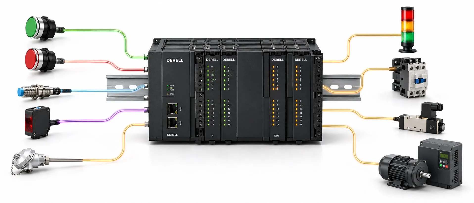
PLC input and output modules connect electrical signals in a machine to its control program. Inputs tell the PLC what is happening in the field; outputs turn the program's commands into suitable electrical signals. For example, an input reports a low tank level, the PLC evaluates the operating conditions, and an output sends a command to start the pump.
The essential division is simple: the input module receives information, the CPU makes the decision, and the output module sends the command. An output being ON does not prove that the connected device is operating. When actual operation must be confirmed, use feedback from an auxiliary contact, sensor or drive status signal.
The four basic I/O types: DI, DO, AI and AO
I/O means input/output. A signal that reports two states is different from one that represents a measured quantity. During PLC programming, the channel type must therefore match the electrical signal provided by the field device.
| Module type | Function | Example |
|---|---|---|
| DI — Digital input | Reads a two-state signal, such as open/closed. | Pushbutton, limit switch or sensor switching output. |
| DO — Digital output | Sends an on/off command to a circuit. | Suitable relay or contactor coil, indicator lamp or valve. |
| AI — Analog input | Converts a measurement signal into a numerical value. | 4–20 mA pressure signal or 0–10 V level signal. |
| AO — Analog output | Produces an adjustable electrical signal from a numerical command. | Drive speed reference or proportional valve command. |
Digital/analog describes the signal; input/output describes its direction relative to the PLC. An analog measurement is also processed as a numerical value inside the CPU.
How does a digital input detect a field signal?
A digital input module evaluates its terminal signal against specified ON/OFF thresholds and provides a 0 or 1 to the program. A limit switch, pushbutton or inductive sensor can supply that signal. 24 V DC inputs are common, but modules do not all use the same voltage. A 24 V input must not be connected to 230 V.
Depending on the module, the input circuit may include filtering and optical isolation. An input filter can reduce the effect of brief interference or mechanical contact bounce, but an excessively long filter time can hide short pulses. Also, isolation does not mean that every channel is independently isolated. Check channel groups and common terminals in the wiring diagram.
Why are PNP and NPN sensors wired differently?
For a typical three-wire DC sensor, an active PNP output supplies current from the positive side of the supply; an active NPN output draws signal current toward 0 V. A PNP sensor is generally paired with a sinking input, while an NPN sensor is paired with a sourcing input. See our NPN versus PNP comparison and guide to sinking and sourcing for the underlying current paths.
The COM/common terminal connection is part of this compatibility. PNP/NPN and NO/NC describe different characteristics. The first identifies the electrical output arrangement; the second describes the output's behavior relative to detection. Two-wire sensors also need separate consideration: leakage current and voltage drop can affect compatibility with the PLC input.
How do analog inputs read temperature, pressure and level?
An analog input module uses an A/D converter to turn a suitable electrical measurement signal into a numerical value. Common ranges include 0–10 V and 4–20 mA. A pressure transmitter, for example, converts pressure into a 4–20 mA signal; the PLC reads the current and converts it into engineering units. When selecting pressure sensors, check the output signal as well as the measurement range.
A temperature sensor cannot automatically be connected to a standard voltage or current input. A Pt100 needs a suitable RTD input module or transmitter; a thermocouple needs a suitable thermocouple module or transmitter. The sensor type, wiring method and module configuration must agree.
A 4–20 mA example: What pressure does 12 mA represent?
Consider a linear 4–20 mA transmitter with a 0–10 bar measurement range. In this example, 4 mA = 0 bar and 20 mA = 10 bar. A reading of 12 mA is halfway through the signal span, so it represents 5 bar.
Pressure (bar) = [(measured current − 4) / 16] × 10
Example: [(12 − 4) / 16] × 10 = 5 bar.
This conversion is called scaling. The module's raw numerical value must first be interpreted using its configured range; raw count ranges are not identical across all PLCs. Also, 0 mA is not a normal zero measurement in a 4–20 mA system: investigate the supply, wiring or device. Signals outside the valid measurement range must be handled according to the device's diagnostic rules.
Digital outputs: Relay, transistor and triac
A relay output switches through a mechanical contact. It can control AC or DC circuits within the contact ratings, but has a limited mechanical life and switching speed. Our guide to how relays work explains the operating principle.
A transistor output switches supported DC circuits electronically. Suitable models can provide rapid switching or pulse generation; verify the PNP/NPN arrangement and voltage and current limits. Not every transistor output is a high-speed pulse output. A triac output is intended for suitable AC loads; the same capabilities must not be assumed for DC loads.
Does the PLC output directly power a motor?
Standard PLC I/O outputs are not used to supply the power circuit of a power motor directly. The PLC usually commands a contactor coil or the control input of a variable frequency drive. The motor's power circuit uses appropriately rated switching and protection equipment. See the difference between a relay and a contactor for more on these separate roles.
Check current per channel, total group current, load inrush and the external field supply. Inductive loads, such as coils, may require suppression devices specified by the manufacturer. An output's current rating does not mean that it can switch every type of load under the same conditions. Short-circuit protection also varies by module.
How does an analog output control drive speed?
An analog output module uses a D/A converter to turn a numerical command into a signal such as 0–10 V or 4–20 mA. If a drive is configured with a linear 0–10 V = 0–50 Hz mapping, 5 V represents a 25 Hz speed reference. This is an example configuration; the actual mapping depends on the drive parameters.
The speed reference and the run command are separate functions. Sending an analog value does not, by itself, mean that the motor will run. Run permission, the selected command source and fault status must also be correct. In pressure or flow regulation, PID control can adjust this reference automatically.
The scan cycle and fast signals
In cyclic operation, the PLC processes input data, application logic and output updates according to its timing arrangement. Many systems use a memory area called the process image to hold I/O values for the program. There is a delay between a physical signal change and the resulting output response. Input filters, program execution, analog conversion and any network update time contribute to that delay. Interrupt tasks and direct I/O access can use different update arrangements.
Fast encoder pulses can be missed if they are counted only through ordinary inputs and program scanning. These applications need a suitable high-speed counter (HSC) or dedicated module. Check the voltage, frequency and electrical interface against the encoder output types. A shorter scan time alone does not guarantee that every pulse will be captured.
Local I/O versus Remote I/O
Local I/O is built into the CPU or installed in its local expansion arrangement. Remote I/O collects field signals elsewhere on the machine and exchanges them with the controller over a communication link. Suitable products may use protocols such as Modbus or EtherCAT. Remote I/O does not eliminate the need for correct analog signal and sensor wiring.
Evaluate output behavior during a network failure through the communication timeout and configured fallback output state. The interface module, network protocol and CPU must be compatible; an I/O module is not automatically interchangeable between PLC systems.
Field example: A pressure-controlled pump
A pressure transmitter can connect to an AI channel, while a level contact confirming water availability connects to a DI channel. The PLC evaluates pressure and operating conditions, then sends a drive run command through a DO and a speed reference through an AO. Drive fault or running status can return through a separate input or communication link.
For simple on/off control, separate start and stop thresholds create hysteresis, reducing repeated switching around a single threshold. PID may be used for continuous speed regulation. An HMI or SCADA system can display pressure and alarms, but a run command shown on a screen does not prove that the pump is turning. Our guide to the relationship between PLCs and SCADA explains the division of responsibilities.
How should you approach an input or output fault?
If an input is missing, check the sensor supply, signal at the correct terminal, common connection, PNP/NPN compatibility and channel address in the program. If an analog reading is wrong, check current/voltage selection, transmitter range, scaling, wiring and interference. Analog signal wiring needs different consideration from power wiring carrying strong switching disturbances. Follow the manufacturer's requirements for shielding and reference connections.
If the output LED is ON but the device does not operate, check the field supply, common terminal, actual output signal, load wiring and any intermediate relay or contactor. The LED does not confirm that the entire power path is intact. During PLC debugging, trace the signal from the field device into the program, then from the program back to the field device. Measurements and wiring changes must be performed by competent personnel under suitable safety conditions.