
How can a burnt component on a circuit board be identified?
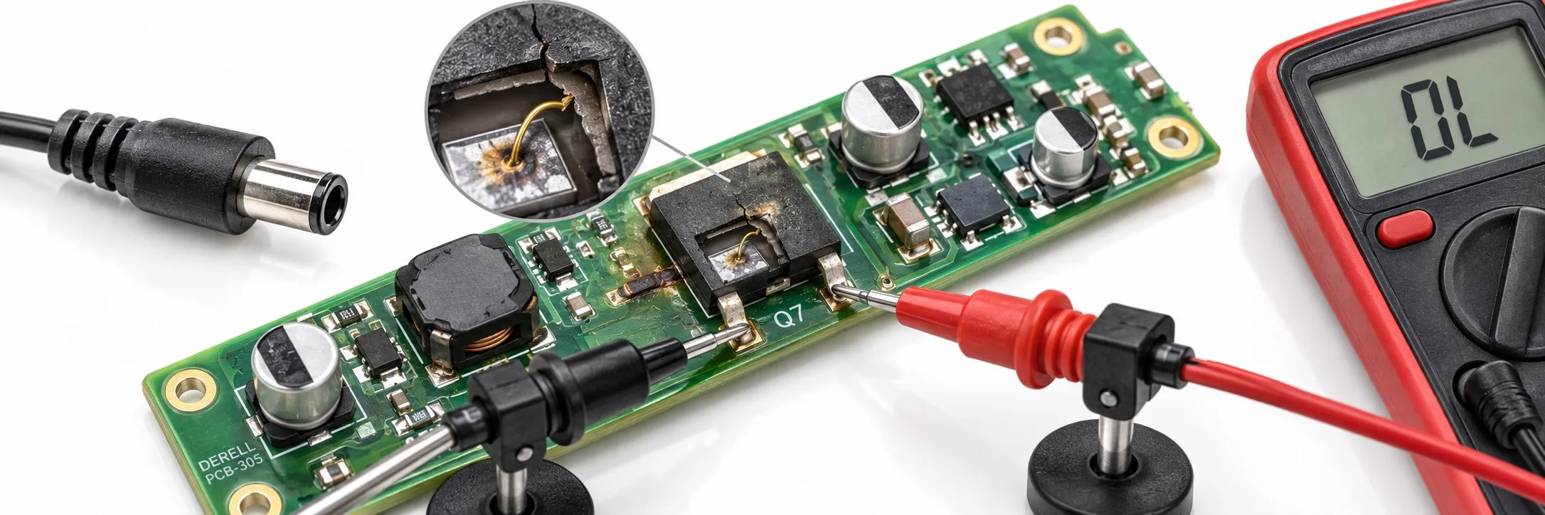
How to identify a burnt component on a circuit board
A cracked package, melted terminal or charred patch can point to a damaged component. Yet appearance alone cannot establish whether a part is electrically healthy. Some failures leave no visible mark, while ordinary soldering residue can look surprisingly similar to heat damage.
Inspection therefore needs to answer two questions: which part has failed, and what caused it to fail? A visibly burnt resistor answers the first question only. Excess current from a fault elsewhere may have destroyed it, so fitting a replacement without checking the surrounding circuit can produce the same failure again.
Make the board safe before inspection
Disconnect every source of power, including batteries and external supplies. Unplugging equipment does not necessarily remove stored energy from its capacitors. Follow the manufacturer's waiting and discharge procedure, and verify that hazardous voltage is absent with suitable test equipment. Do not discharge capacitors by shorting their terminals with a screwdriver. Work on mains circuitry and equipment with substantial stored energy requires appropriate training and equipment.
What does genuine component damage look like?
Resistors: Blistered coating, a split body or pronounced scorching around the leads suggests overheating. Discoloration does not reveal the original resistance or explain why the part overheated. Even a measurable resistance on a burnt part may be far from its original value.
Capacitors: A bulging aluminium electrolytic capacitor, an opened pressure vent or leaking electrolyte indicates damage. However, lost capacitance and increased ESR can occur without visible swelling. Ceramic capacitors can also crack or fail short with little external evidence. See how to identify a faulty capacitor for the distinction between visible symptoms and electrical failure.
Semiconductors: A hole in an IC package, a fractured diode body or a damaged lead is clear physical evidence. Conversely, a MOSFET may fail short while its case looks untouched. A clean exterior is not a pass result.
Connectors and copper tracks: Melted housings, darkened contacts, lifted pads and broken tracks deserve the same attention as damaged electronic parts. Local heating at a connector can result from a loose or contaminated contact. Inspect both sides of the board and the mating connections rather than concentrating only on the most obvious blackened component.
Distinguish scorching from residue and ageing
Amber or brown material around a solder joint may be flux residue. Heat can darken it further, making an undamaged joint look burnt in a photograph. Consider the condition of the component body, copper and board laminate together. Understanding flux, solder wire and desoldering tools helps explain where these deposits come from.
A brown patch beneath a power resistor may reflect prolonged exposure to heat rather than an electrically failed resistor. Charred laminate, separated board layers or damaged copper is a more serious finding. Carbonisation can compromise insulation, so replacing the nearby component alone may leave an unreliable or unsafe board.
A ring-shaped crack around a lead points towards a solder connection problem. This is discussed in cold solder joints and how to identify them. If cleaning is needed, check compatibility with the board materials and protective coating: contact cleaner is not universally suitable for electronics.
Use measurements to investigate the suspected fault
Identify the component and its function first. Reference designators such as R, C, D, Q, U and F provide useful clues, but the schematic and component markings take priority. A measurement is meaningful only when you understand what is being measured and what behaviour the circuit should show.
Resistance and continuity: Other components can create parallel paths during an in-circuit resistance measurement. Isolating one lead or removing the part may be necessary. A continuity buzzer merely indicates resistance below the meter's threshold. A beep does not automatically mean a short circuit: healthy windings and other low-resistance paths may also trigger it.
Diodes and junctions: A diode test can help compare forward and reverse behaviour once the circuit is safe. Parallel paths can complicate the result, and different device types have different expected readings. A standard diode, a Schottky diode and a MOSFET body diode should not all be judged against one fixed voltage. Passing this basic test also does not establish correct behaviour at operating voltage.
Capacitors: After safe discharge, measuring capacitance can reveal some faults. A correct capacitance reading does not establish acceptable ESR, leakage or performance under load. Choose further tests according to the capacitor technology and its function in the circuit.
What if the component marking has burnt off?
Do not select a replacement by appearance. Use the service schematic, bill of materials or verified information for the exact board revision. An apparently identical channel on the same board may provide a comparison, but matching layouts do not guarantee matching component values.
Replacement specifications extend beyond the headline value. Resistors may need a particular pulse rating or fusible construction. Capacitors have temperature, ripple-current and ESR requirements. Semiconductors also need the correct pinout and suitable switching characteristics. Installing a higher-wattage part to stop it burning can defeat an intended protective function.
Why can a replacement fail immediately?
Consider a resistor feeding a shorted section of circuitry. Replacing the resistor leaves the excessive current demand in place. Likewise, investigation of a failed power MOSFET may need to include its drive circuit, associated protection components and load. For a board that will not start, follow the fault through the supply stages described in circuit board power faults.
A blown fuse or damaged varistor can also be the consequence of another fault. Varistors, TVS diodes and fuses perform different protective functions. Never bridge a fuse or increase its current rating to keep equipment running. Re-energising belongs to a controlled service procedure after the cause has been investigated.
What if there is a burning smell but no visible damage?
The source may be a connector, relay contact, winding insulation or an obscured part of the assembly. Smell alone cannot identify the failed component. Do not repeatedly power equipment that has developed a burning smell, smoke or melting. Continued operation does not demonstrate that it is safe.