
What types of sensors are compatible with the device?
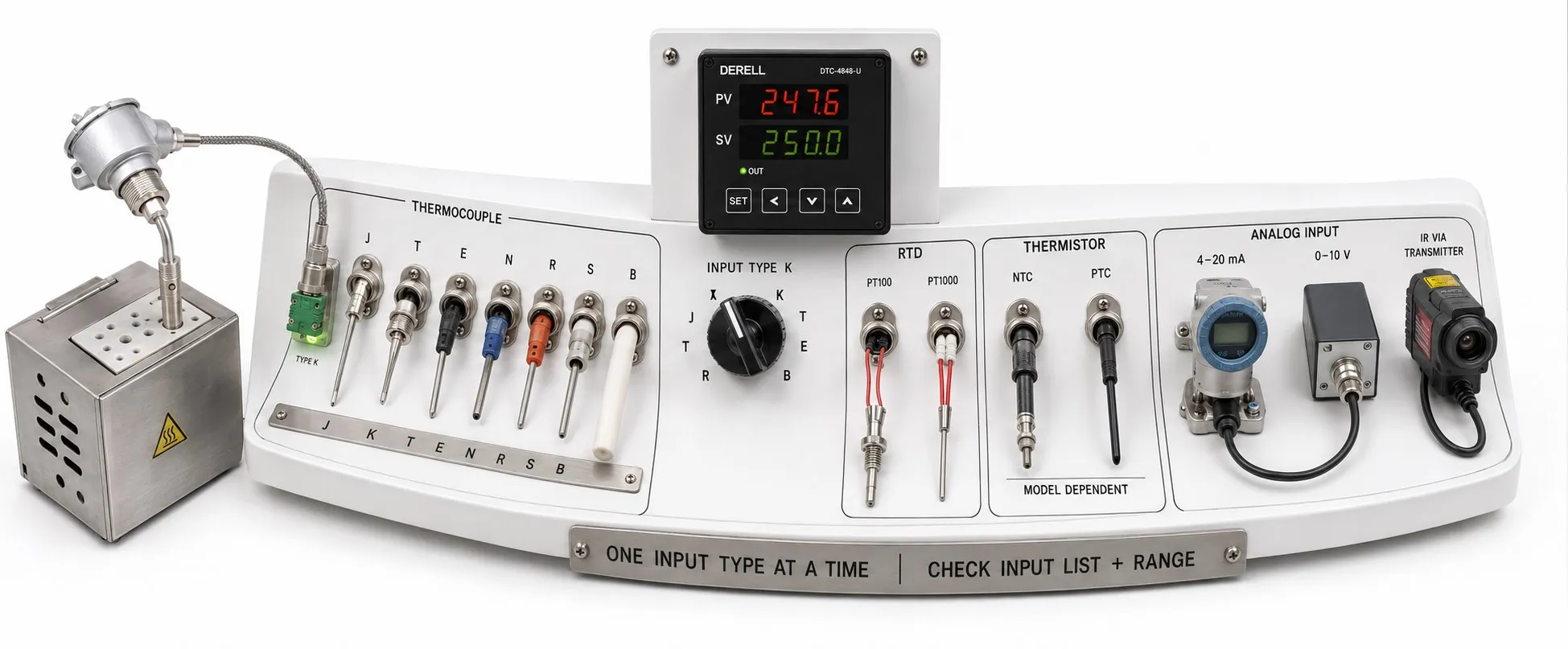
The controller's input circuit matters as much as the sensor name
Hello, a temperature controller works only with the sensor types and input signals specified in its documentation. Thermocouple, RTD, thermistor and analogue input support depends on the complete model code and input hardware. “Universal input” does not mean every sensor is supported; check the individual input types.
Editor's note: Matching wire counts do not establish compatibility. A two-wire thermocouple, two-wire Pt100 and two-wire 4–20 mA transmitter require different inputs. A menu setting alone cannot convert unsuitable input hardware.
Thermocouples: match the letter designation
A thermocouple generates a small voltage related to its measuring and reference junction temperatures. The manual identifies supported types, such as K, J, T, E, N, R, S or B. A type K sensor connected to an input configured for type J will not give correct measurements because the voltage-temperature relationships differ.
Polarity, suitable extension or compensating cable and cold-junction compensation must be correct. A metal sheath or wire colour alone is not a definitive type identification. Grounded or insulated junction construction must also be assessed against the application's grounding and isolation requirements.
RTD inputs: Pt100 and Pt1000 are not interchangeable
A Pt100 element has a nominal resistance of 100 Ω at 0 °C, while a Pt1000 has 1000 Ω at 0 °C. Both are platinum RTDs, but they cannot use the same input configuration. The supported resistance-temperature characteristic must also match; “platinum sensor” is not a sufficient specification.
Check which two-, three- or four-wire RTD arrangements the controller accepts. Lead resistance can introduce error in two-wire measurements. Three-wire compensation depends on matched lead resistances; four-wire measurement requires a four-wire-capable input. Follow the manufacturer's terminal diagram.
NTC and PTC thermistors: nominal resistance is not enough
An NTC sensor's resistance falls as temperature rises. Two NTCs rated 10 kΩ at 25 °C can have different B values and resistance-temperature curves. Match the nominal resistance, reference temperature, curve and tolerance. Support for one NTC curve does not establish support for others.
A PTC sensor's resistance rises with temperature, but PTC devices are not all used in the same way for continuous temperature measurement. A motor-protection PTC, in particular, may be intended for threshold detection. Do not assume it can connect directly to a standard temperature control input.
With a transmitter, match the output signal
A Pt100 or thermocouple can connect to a temperature transmitter that converts its signal into 4–20 mA, 0–10 V or another standard signal. The controller then reads the transmitter output rather than the raw sensor. Current or voltage input support, power and loop wiring must be suitable; verify any required input hardware or terminal selection.
For example, with a transmitter configured as 0–400 °C = 4–20 mA, 12 mA represents 200 °C. The controller's lower and upper scaling limits must match. Changing the temperature setpoint does not automatically correct analogue input scaling. Assess the sensor range, input scaling and setting limits separately.
How do infrared and semiconductor sensors connect?
An infrared pyrometer can connect through a suitable analogue output or supported digital interface. Besides the output type, consider the measurement range, emissivity and measurement spot. An alarm relay may provide threshold status only; it is not a substitute for a continuous temperature value.
Semiconductor temperature sensors may provide analogue voltage or use digital interfaces such as I²C, SPI or 1-Wire. These are not automatically compatible with standard panel controller sensor inputs. Suitable interface electronics, a transmitter or communications support may be needed. Check the sensor's supply requirements as well.
After electrical compatibility, assess the application
The sensor and controller input must both cover the required temperatures. A displayed maximum temperature does not prove the sensor can withstand it. Assess the required measurement accuracy, response time, immersion depth, sheath material and mounting arrangement. Sensor process conditions differ from the controller's cabinet ambient conditions.
What should be verified during commissioning?
After checking the sensor code, input type, wiring, units and scaling, compare against a reference at suitable points across the working range. One plausible reading does not prove compatibility. Test open-circuit detection and the output action on sensor failure according to the manual. Investigate sensor and wiring errors before applying an offset to an unexpected reading.
When selecting a controller, assess the complete sensor code and output type together. If direct support is unavailable, a suitable transmitter may provide a solution, but conversion adds its own error, power and configuration requirements.
Temperature sensors | Temperature controllers | Temperature controller FAQ | Temperature controller prices